Ford F150 Fuse Box Diagram (1999 to 2021)
There are plenty of electrics in a Ford F150 which means there are a lot of things that can possibly go wrong as well. A common cause of electrical failures in your truck could lead back to the fuse box so it is important to understand what you are looking at.
In this post we will hit each year's Ford F150 since 1999 to explain to you the layout of the fuse box. Some may be similar to the previous year but as manufacturers are always improving you will see differences over time.
The 1999 Ford F150 Fuse Boxes Diagram and Explanation
In the 1999 Ford F150 there were essentially two different fuse boxes: the one found in the passenger compartment and the Power Distribution Fuse Box. In the following two tables I will explain both of these fuse boxes and what each fuse equates to.
Passenger Compartment Fuse Box
The Passenger Compartment Fuse Box in the Ford F150 is located under the steering wheel to the left hand side. It is behind a removable cover near the brake pedal. You merely have to remove this cover to gain access to the fuses to check they have not burned out.
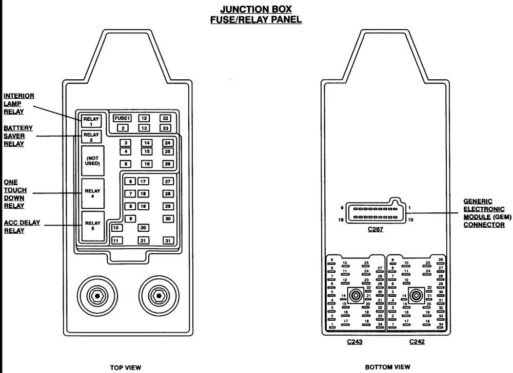
|
Fuse Number
|
Fuse Amperage
|
Fuse Function
|
|
1
|
15A
|
Audio Section
|
|
2
|
5A
|
Handling cluster and Powertrain Control Module (PCM)
|
|
3
|
20A
|
OBD-II Scan Tool Connecter & cigarette lighter
|
|
4
|
15A
|
Mirrors, Auto lamp and remote entry module
|
|
5
|
15A
|
Reverse lamp. Speed control module, climate mode switch, AC, clutch relay and daytime running lamps
|
|
6
|
15A
|
GEM module. rear air suspension module, brake shift interlock solenoid
|
|
7
|
|
Not in Use
|
|
8
|
5A
|
GEM module, remote entry module and radio
|
|
9
|
|
Not in Use
|
|
10
|
|
Not in Use
|
|
11
|
30A
|
Windshield wiper motor, wiper run/park relay, front washer pump relay and wiper hi/lo relay
|
|
12
|
|
Not in Use
|
|
13
|
20A
|
Speed control module. stop lamp switch and turn/hazard flasher
|
|
14
|
15A
|
Accessory delay relay, interior lamp relay and battery saver relay
|
|
15
|
5A
|
RABS test connector, GEM module, stop lamp switch, speed control, ABS, PCM module inputs and brake shift interlock
|
|
16
|
20A
|
Clusters and headlamps for both sides
|
|
17
|
|
Not in Use
|
|
18
|
5A
|
Instrument illumination
|
|
19
|
|
Not in Use
|
|
20
|
5A
|
PCM, audio and GEM module
|
|
21
|
15A
|
Starter relay and clutch switch
|
|
22
|
10A
|
Passenger airbag deactivation module and airbag module
|
|
23
|
10A
|
4x4 relays, 4x4 solenoids, trailer low battery charge relay and turn/hazard flasher
|
|
24
|
10A
|
Blower relay
|
|
25
|
5A
|
4-wheel anti-lock brake system module (4WABS)
|
|
26
|
10A
|
Right side low beam headlamp
|
|
27
|
5A
|
Fog Lamp indicator and fog lamp relay
|
|
28
|
10A
|
Left side low beam headlamp
|
|
29
|
5A
|
Transmission overdrive control switch, auto lamp module
|
|
30
|
30A
|
Powertrain control module (PCM) relay, cluster, ignition coils and passive anti-theft transceiver
|
|
31
|
|
Not in Use
|
|
Relay 1
|
|
Interior lamp
|
|
Relay 2
|
|
Battery saver
|
|
Relay 3
|
|
Not in Use
|
|
Relay 4
|
|
One touchdown window
|
|
Relay 5
|
|
ACC delay
|
You will notice there are several fuses that are not used for anything and that some systems have multiple fuses. If the system you are checking uses multiple fuses be sure to check them all.
Power Distribution Fuse Box
The Power Distribution Fuse Box is not found in the vehicle's cabin but instead can be located under the hood. It is on the left hand side of the engine compartment under a protective cover. You will have to remove this cover to gain access to the fuses.
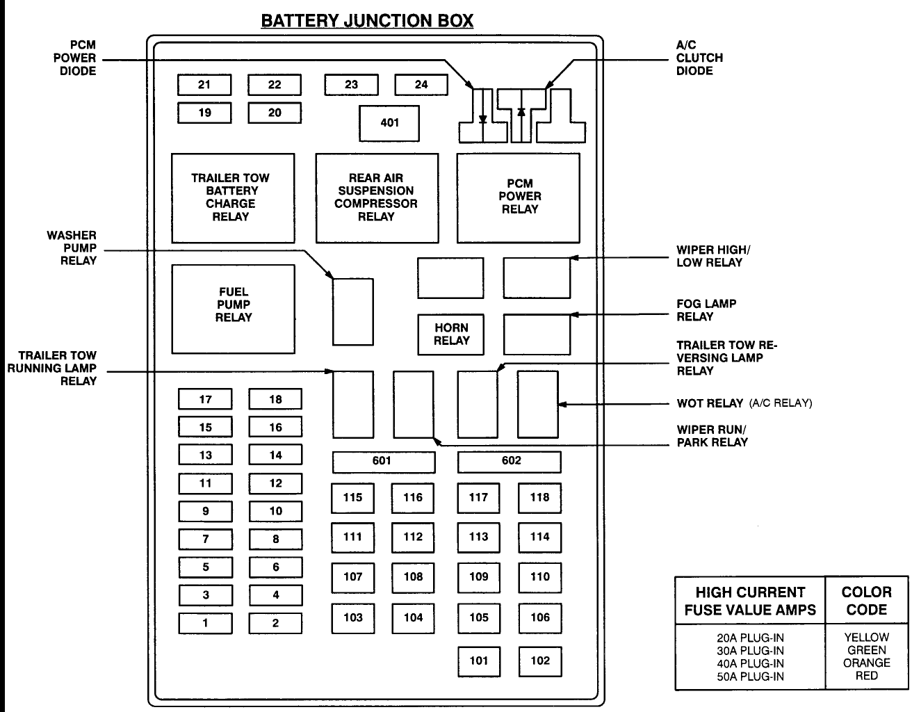
|
Fuse Number
|
Fuse Amperage
|
Fuse Function
|
|
1
|
25A
|
Powerpoint
|
|
2
|
30A
|
Handling powertrain control module
|
|
3
|
30A
|
Headlamps or auto lamps
|
|
4
|
15A
|
Air suspension
|
|
5
|
20A
|
Park lamps and trailer tow backup
|
|
6
|
15A
|
Park lamps or auto lamps
|
|
7
|
15A
|
The horn
|
|
8
|
15A
|
Power door locks
|
|
9
|
15A
|
Daytime running lamps and fog lamps
|
|
10
|
20A
|
Fuel pump
|
|
11
|
20A
|
Alternator field
|
|
12
|
|
Not in Use
|
|
13
|
|
Not in Use
|
|
14
|
|
Not in Use
|
|
15
|
|
Not in Use
|
|
16
|
|
Not in Use
|
|
17
|
|
Not in Use
|
|
18
|
15A
|
Mass airflow sensor, fuel injectors, PCM and fuel pump
|
|
19
|
10A
|
Right turn lamp and trailer tow stop
|
|
20
|
10A
|
Left turn lamp and trailer tow stop
|
|
21
|
|
Not in Use
|
|
22
|
|
Not in Use
|
|
23
|
15A
|
The heated exhaust gas oxygen sensor (HEGO), canister vent and PCM
|
|
24
|
15A
|
Continuous monitoring system (CMS) sensor, PCM and automatic transmission
|
|
101
|
30A
|
Trailer tow battery charge
|
|
102
|
50A
|
Rear wheel or 4-wheel antilock brake modules
|
|
103
|
50A
|
Junction block battery feed
|
|
104
|
30A
|
4x4 shift motor and clutch
|
|
105
|
40A
|
Climate control front blower
|
|
106
|
|
Not in Use
|
|
107
|
|
Not in Use
|
|
108
|
30A
|
Trailer tow electric brake
|
|
109
|
50A
|
Air suspension compressor
|
|
110
|
30A
|
Power Windows
|
|
111
|
50A
|
Ignition switch for start and run circuits
|
|
112
|
30A
|
Drivers power seat
|
|
113
|
50A
|
Ignition switch battery feed
|
|
114
|
|
Not in Use
|
|
115
|
|
Not in Use
|
|
116
|
|
Not in Use
|
|
117
|
|
Not in Use
|
|
118
|
|
Not in Use
|
|
Relay 201
|
|
Trailer tow park
|
|
Relay 202
|
|
Front wiper run/park
|
|
Relay 203
|
|
Trailer tow backup lamp
|
|
Relay 204
|
|
A/C clutch
|
|
Relay 205
|
|
Horn
|
|
Relay 206
|
|
Fog Lamp
|
|
Relay 207
|
|
Front washer pump
|
|
Relay 208
|
|
Not in Use
|
|
Relay 209
|
|
Front wiper lo/hi
|
|
Relay 301
|
|
Fuel pump
|
|
Relay 302
|
|
Trailer tow battery charge
|
|
Relay 303
|
|
Rear air suspension
|
|
Relay 304
|
|
Powertrain control module (PCM)
|
|
Relay 401
|
|
Not in Use
|
|
ATO Diode 501
|
|
PCM
|
|
ATO Diode 502
|
|
A/C clutch
|
|
ATO Diode 503
|
|
Not in Use
|
|
Circuit Breaker 601
|
|
Not in Use
|
|
Circuit Breaker 602
|
|
Not in Use
|
2000 Ford F150 Fuse Box Diagram and Explanation
In the 2000 model year of the Ford F150 there were again two different fuse boxes, one in the passenger compartment and the other under the hood.
Passenger Compartment Fuse Box
Just as in 1999, the Passenger Compartment Fuse Box entry will be found below the steering wheel close to the brake pedal. Simply by removing the covering panel you can access these fuses to check and change them if needs be.
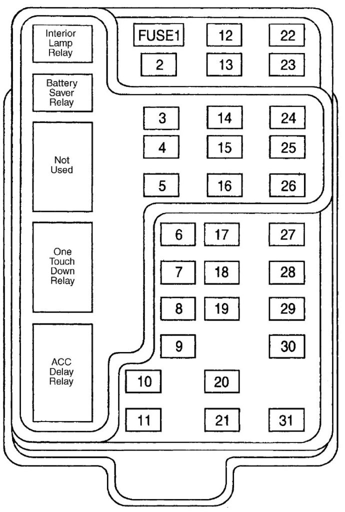
|
Fuse Number
|
Fuse Amperage
|
Fuse Function
|
|
1
|
15A
|
Audio section
|
|
2
|
5A
|
Cluster, powertrain control module (PCM)
|
|
3
|
20A
|
OBD-II Scan Tool connecter port and cigarette lighter
|
|
4
|
15A
|
Mirrors, remote entry module and auto lamp module
|
|
5
|
15A
|
Speed control module, reverse lamp, daytime running lamp relay and climate mode switch
|
|
6
|
5A
|
Cluster, GEM module and brake shift interlock solenoid
|
|
7
|
|
Not in Use
|
|
8
|
5A
|
GEM module, remote entry module and radio
|
|
9
|
|
Not in Use
|
|
10
|
|
Not in Use
|
|
11
|
30A
|
Windshield wiper motor, wiper run/park relay, front washer pump relay and wiper hi/lo relay
|
|
12
|
|
Not in Use
|
|
13
|
20A
|
Speed control module. stop lamp switch and turn/hazard flasher
|
|
14
|
15A
|
Accessory delay relay, interior lamp relay and battery saver relay
|
|
15
|
5A
|
RABS test connector, GEM module, stop lamp switch, speed control, ABS, PCM module inputs and brake shift interlock
|
|
16
|
20A
|
Clusters and headlamps for both sides
|
|
17
|
|
Not in Use
|
|
18
|
5A
|
Instrument illumination
|
|
19
|
|
Not in Use
|
|
20
|
5A
|
Power train module, audio and CTM or GEM module
|
|
21
|
15A
|
Starter relay and clutch switch
|
|
22
|
10A
|
Passenger airbag deactivation module, airbag module and blower relay
|
|
23
|
10A
|
4x4 relays, 4x4 solenoids, trailer tow battery charge relay, 4-wheel anti-lock brakes module, overhead console and turn/hazard flasher
|
|
24
|
|
Not in Use
|
|
25
|
|
Not in Use
|
|
26
|
10A
|
Right side low beam headlamp
|
|
27
|
5A
|
Fog Lamp indicator and fog lamp relay
|
|
28
|
10A
|
Left side low beam headlamp
|
|
29
|
5A
|
Transmission overdrive control switch, auto lamp module
|
|
30
|
30A
|
Powertrain control module (PCM) relay, cluster, ignition coils and passive anti-theft transceiver
|
|
31
|
|
Not in Use
|
|
Relay 1
|
|
Interior lamp
|
|
Relay 2
|
|
Battery saver
|
|
Relay 3
|
|
Not in Use
|
|
Relay 4
|
|
One touchdown window
|
Power Distribution Fuse Box
This again as in the 1999 model can be found on the left hand side of the engine bay and can be accessed by removing the protective cover.
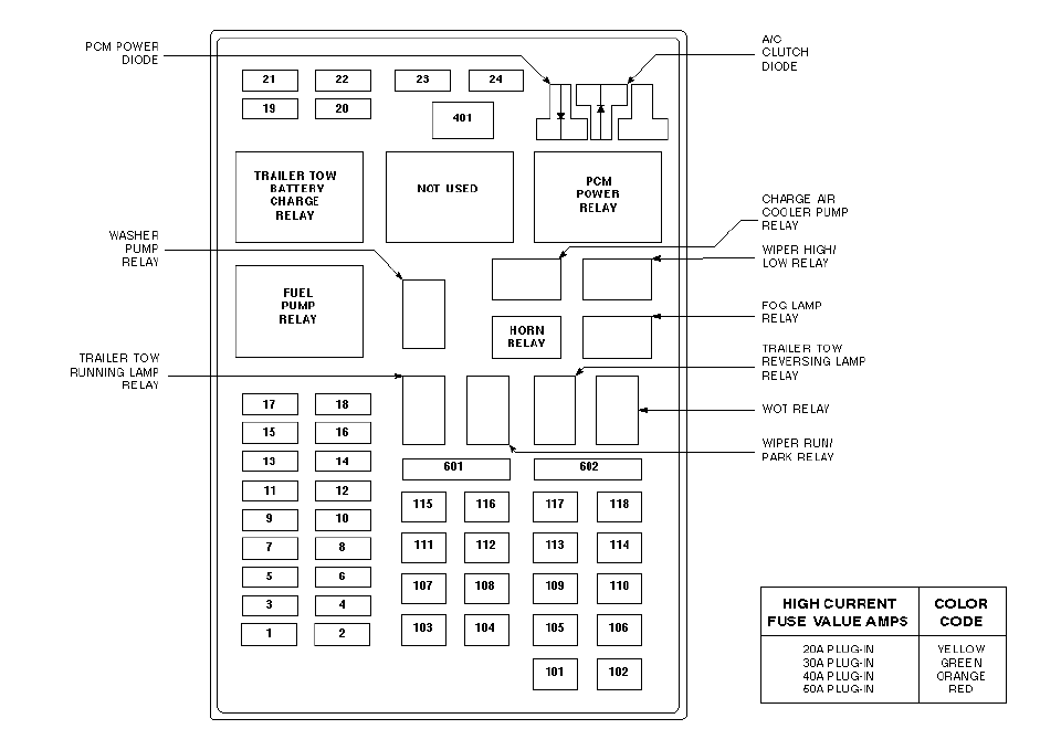
|
Fuse Number
|
Fuse Amperage
|
Fuse Function
|
|
1
|
20A
|
Powerpoint
|
|
2
|
30A
|
Handling powertrain control module
|
|
3
|
30A
|
Headlamps or auto lamps
|
|
4
|
15A
|
Not in Use
|
|
5
|
20A
|
Park lamps and trailer tow backup
|
|
6
|
15A
|
Park lamps, auto lamps and #18 of passenger fuse panel feed
|
|
7
|
15A
|
The horn
|
|
8
|
15A
|
Power door locks
|
|
9
|
15A
|
Daytime running lamps and fog lamps
|
|
10
|
20A
|
Fuel pump
|
|
11
|
20A
|
Alternator field
|
|
12
|
20A
|
Rear auxiliary powerpoint
|
|
13
|
15A
|
A/C clutch
|
|
14
|
|
Not in Use
|
|
15
|
|
Not in Use
|
|
16
|
|
Not in Use
|
|
17
|
|
Not in Use
|
|
18
|
15A
|
Mass airflow sensor, fuel injectors, power control module and fuel pump, idle air controller
|
|
19
|
10A
|
Right turn lamp and trailer tow stop
|
|
20
|
10A
|
Left turn lamp and trailer tow stop
|
|
21
|
|
Not in Use
|
|
22
|
|
Not in Use
|
|
23
|
15A
|
The heated exhaust gas oxygen sensor (HEGO), canister vent and PCM
|
|
24
|
|
Not in Use
|
|
101
|
30A
|
Trailer tow battery charge
|
|
102
|
50A
|
Rear wheel or 4-wheel antilock brake modules
|
|
103
|
50A
|
Junction block battery feed
|
|
104
|
30A
|
4x4 shift motor and clutch
|
|
105
|
40A
|
Climate control front blower
|
|
106
|
20A
|
Intercooler pump, lighting only
|
|
107
|
|
Not in Use
|
|
108
|
30A
|
Trailer tow electric brake
|
|
109
|
50A
|
Not in Use
|
|
110
|
30A
|
Power Windows
|
|
111
|
40A
|
Ignition switch battery feed for start and run circuits
|
|
112
|
30A
|
Drivers power seat and adjustable pedals
|
|
113
|
40A
|
Ignition switch battery feed
|
|
114
|
|
Not in Use
|
|
115
|
20A
|
Power door locks on SuperCrew only
|
|
116
|
|
Not in Use
|
|
117
|
|
Not in Use
|
|
118
|
|
Not in Use
|
|
Relay 201
|
|
Trailer tow park
|
|
Relay 202
|
|
Front wiper run/park
|
|
Relay 203
|
|
Trailer tow backup lamp
|
|
Relay 204
|
|
A/C clutch
|
|
Relay 205
|
|
Horn
|
|
Relay 206
|
|
Fog Lamp
|
|
Relay 207
|
|
Front washer pump
|
|
Relay 208
|
|
Not in Use
|
|
Relay 209
|
|
Front wiper lo/hi
|
|
Relay 301
|
|
Fuel pump
|
|
Relay 302
|
|
Trailer tow battery charge
|
|
Relay 303
|
|
Not in Use
|
|
Relay 304
|
|
Powertrain control module (PCM)
|
|
Relay 305
|
|
Fuel pump hi/lo
|
|
Relay 306
|
|
Interior switch
|
|
ATO fuse 401
|
|
Not in Use
|
|
ATO Diode 501
|
|
PCM
|
|
ATO Diode 502
|
|
A/C compressor
|
|
ATO Diode 503
|
|
Not in Use
|
|
Circuit Breaker 601
|
|
Power windows and moonroof for SuperCrew
|
|
Fuse 602
|
|
Not in Use
|
You will likely note that both sets of fuses are very similar to the 1999 Ford F150 model but there have been some noticeable changes. A few redundant fuses have been put to use with new features while some systems have been merged through a single fuse freeing up other fuses to be no longer used.
2001 Ford F150 Fuse Box Diagrams and Explanations
As before, the F150 in this model year features two fuse boxes that are located in essentially the same places as in the 1999 and 2000 model years.
To this point we have been using tables to display the fuse functions but it may be more expeditious to continue on with explaining the changes from the previous fuse box layouts.
Passenger Compartment Fuse Box
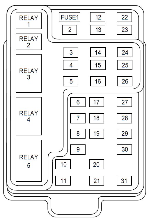
What Has stayed the same?
- Fuses 1 – 3
- Fuses 7 – 14
- Fuses 16 – 19
- Fuses 26 – 31
- All Relays remain the same
What Has changed?
- Fuse number 4 is a 5A which controls the remote entry modules and power mirrors
- Fuse number 5 is a 15A and controls the speed control module, daytime running lamp relay, climate mode switch and reverse lamp
- Fuse number 6 is a 5A which now controls the cluster, GEM module, and the brake interlock solenoid
- Fuse number 15 is a 5A which also controls the GEM module and brake shift interlock as well as the anti-lock brakes, powertrain control module (PCM), stop lamp switch and speed control module
- Fuse number 20 is a 5A that now controls the PCM, audio and GEM or CTM modules
- Fuse number 21 is a 15A that handles fuse 20 as well as the starter relay
- Fuse number 22 is a 10A which handless the blower relay, airbag module and climate mode switch
- Fuse number 23 is a 10A which handles the 4x4 solenoids, 4x4 relays, overhead console, 4-wheel anti-lock brakes module (4WABS), turn/hazard flasher and the trailer tow battery charge relay
- Fuse numbers 24 & 25 that controlled the blower relay and 4WABS respectively in the 1999 model year are now not in use.
Power Distribution Box
When you compare the 2001 model year Power Distribution Fuse Box to that in the 1999 Ford F150 truck you will see many similarities and a few notable changes.
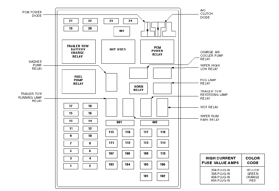
What Has Stayed the Same?
- Fuses 2, 3 and 5 have not changed from 1999
- Fuses 9 – 11 have not changed
- Fuses 14 - 17 have not changed
- Fuses 19 - 22 have not changed
- Fuses 101 – 108 have not changed
- Fuse 114 stays the same
- Fuses 116 - 118 have not changed
- Relays 201 – 209 have not changed
- Relays 301 and 302 have not changed
- Diodes 501 and 503 have not changed
What Has Changed?
- Fuse number 1 is now a 20A instead of 25A but still control the powerpoint
- Fuse number 4 used to be air suspension but is now not used
- Fuse number 6 is 15A and handles auto lamps, park lamps and the .18 fuse from the passenger fuse panel feed
- Fuse number 7 is now a 20A that handles the horn
- Fuse number 8 is no longer used
- Fuse number 12 is a 20A used for rear auxiliary powerpoint
- Fuse number 13 is a 15A that controls the A/C clutch
- Fuse number 18 is a 15A that controls the mass air flow sensor, fuel injection, power control module, fuel pump relay and now additionally the idle air control
- Fuse number 23 is 15A and covers the HEGO sensor, canister vent and automatic transmission it formerly also covered the PCM but does not anymore
- Fuse number 24 is no longer used
- Fuse number 102 is a 50A that works with the 4-wheel anti-lock brake module
- Fuses number 109 & 110 are both no longer in use
- Fuse number 111 is a 40A which works with the ignition switch battery feed for the start & run circuits
- Fuse number 112 is a 30A which works with the drivers side power seats and the adjustable pedals
- Fuse number 113 is a 40A which controls the ignition switch battery feed
- Fuse number 115 is a 20A used for the power door locks
- Relay number 303 is no longer being used
- Relay number 304 is used for the powertrain control module
- Relays number 305 and 306 is are no longer being used
- ATO fuse number 401 is not being used
- ATO diode number 502 is being used for the compressor
- Circuit breaker 601 is 30A and is used for power windows and the moonroof
- Fuse number 602 is no longer being used
2002 Ford F150 Fuse Box Diagrams and Explanation
Consistently there are two fuse boxes featured in the 2002 model Ford F150 just as in previous years and they are located in roughly the same places within the truck itself.
Passenger Compartment Fuse Box
The consistency continues with many of the fuses remaining the same from the 1999 model Ford F150 truck although there are some notable changes that should be mentioned.
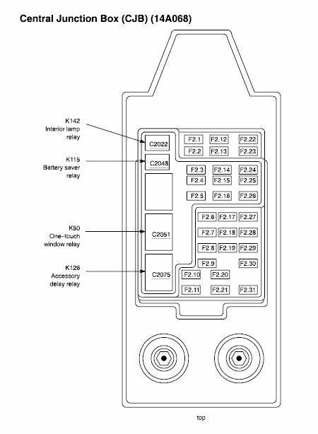
What Stays the Same?
- Fuses 1, 2 and 7 remain the same
- Fuses 9 – 12 remain the same
- Fuses 16 – 19 remain the same
- Fuses 22, 26, 28, and 31 remain the same
- All of the relays remain unchanged
What Has Changed?
- Fuse number 3 is a 20A that is used for the data link connector and cigarette lighter
- Fuse number 4 is a 5A that is used for the exterior rearview mirror switch and mirror turn signal relays
- Fuse number 5 is a 15A used for daytime running lamp relay, Digital Transmission Range sensor, AC clutch relay, climate mode switch, speed control module and reverse lamp
- Fuse number 6 is a 5A used for the General Electric Module (GEM), cluster and the brake shift interlock solenoid
- Fuse number 8 is a 5A used for the GEM. In-vehicle entertainment system (SuperCrew and radio only) and remote entry module
- Fuse number 13 is a 20A which helps operate the stop lamp switch and turn/hazard flasher
- Fuse number 14 is a 15A that works with the battery saver relay and interior lamp relay
- Fuse number 15 is a 5A that assists the anti-lock electronic control module (RABS), GEM, speed control, stop lamp switch and brake shift interlock
- Fuse number 20 is a 5A used for the powertrain control module (PCM), GEM, audio and transmission range sensor
- Fuse number 21 is a 15A that handles the starter relay, DTR sensor, clutch switch and instrument panel fuse .20
- Fuse number 23 is a 10A that deals with 4-wheel anti=lock brake system (4WABS) module, electrochromic mirror, 4x4 solenoids, 4x4 relays, turn/hazard flasher and tow battery charge relay
- Fuse number 24 is a 10A which assists the function selector switch assembly
- Fuse number 25 is no longer in use
- Fuse number 27 is a 5A which is sued for the fog lamp relay, foglamp indicator and the upstream main light switch
- Fuse number 29 is a 5A that assists the auto lamp module, central security module, belt minder and the transmission overdrive control switch
- Fuse number 30 is a 30A which runs the coils on plug, passive anti-theft transceiver, radio noise capacitor, ECC diode, PCM relay and the cluster
Power Distribution Fuse Box
There are some notable changes to the Power Distribution Fuse Box from the 1999 Ford F150 model but there are also many fuses that have remained unchanged.
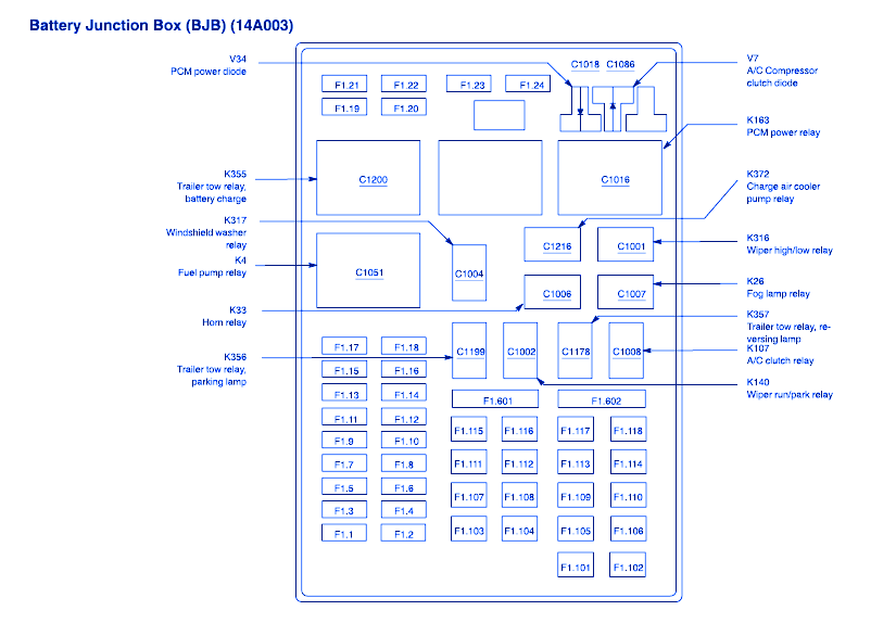
What Stayed the Same?
- Fuses 2, 5 and 7 stayed the same
- Fuses 9 – 11 stayed the same
- Fuse 14 stayed the same
- Fuses 16 – 18 stayed the same
- Fuses 21, 22, 101, 104, 105, 107, 108, 114, 116 and 117 all stayed the same
- Relays 201 to 207 stayed the same
- Relays 209, 301, 302 and 304 stayed the same
- Diodes 501 and 503 also remained unchanged
What Changed?
- Fuse number 1 is a 25A that is used to control the powerpoint
- Fuse number 3 is a 30A used for the multifunction switch, main light switch and headlamps relay
- Fuse number 4 is no longer in use
- Fuse number 6 is a 15A used for the main light switch and park lamp relay
- Fuse number 8 is a 15A that deals with the lock relays, CSM and power door locks
- Fuse number 12 is a 20A designed for the rear auxiliary powerpoint
- Fuse number 13 is a 15A used for the A/C clutch
- Fuse number 15 is a 10A used for the running board lamps
- Fuse number 19 is a 10A used for the right stop and turn lamp trailer/camper adapter
- Fuse number 20 is a 10A used for the left stop and turn lamp trailer/camper adapter
- Fuse number 23 is a a15A that controls the automatic transmission and the heated exhaust gas oxygen sensor (HEGO)
- Fuse number 24 is no longer in use
- Fuse number 102 is a a 50A used for the ignition switch and the rear wheel antilock brake or 4-wheel anti lock brake modules
- Fuse number 103 is a 50A that controls the central junction box
- Fuse number 106 is a 20A that assists the intercooler pump (supercharged engines only)
- Fuse number 109 is no longer in use
- Fuse number 110 is a 30A for the ACC delay relay
- Fuse number 111 is a 40A for the ignition switch battery feed for the start and run circuits
- Fuse number 112 is a 30A for the adjustable pedals and drivers power seat
- Fuse number 113 is a 40A for the ignition switch battery feed
- Fuse number 115 is a 20A for the power door locks
- Fuse 118 is a 30A used for the heated seats
- Relay 208 is for the intercooler pump (supercharged engines only)
- Relay 303 is not in use
- Relay 305 is for the hi/lo fuel pump (supercharged engines only)
- Relay 306 is for the inertia switch in supercharged engine trucks
- ATO Fuse number 401 is not in use
- Diode 502is for the A/C compressor
- Circuit breaker 601 runs the power windows and moonroof
- Fuse 602 is not in use
You will likely notice some notable new features added in the 2002 Ford F150 such as the entertainment system. This is a trend that progresses over the years and you will note more and more innovation reflected in the new fuses.
2003 Ford F150 Fuse Box Diagrams and Explanations
The fuse box diagram for the Ford 2003 F150 is going to look familiar however some of the fuse allocations will seem different. In this section we will switch briefly back to a graph layout to give you a clearer visual representation of the changes.
There are still two fuse boxes in this model year and you will find them in the same places as in previous years.
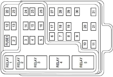
|
Fuse Number
|
Fuse Amperage
|
Fuse Function
|
|
1
|
15A
|
Audio Section
|
|
2
|
5A
|
Handling cluster and Powertrain Control Module (PCM)
|
|
3
|
20A
|
Data link Connecter & cigarette lighter
|
|
4
|
5A
|
Mirrors turn signal relays, power motor switches
|
|
5
|
15A
|
Reverse lamp. Speed control module, climate mode switch, AC, Digital Transmission Range sensor and daytime running lamps
|
|
6
|
5A
|
General Electric Module (GEM), cluster, brake shift interlock solenoid
|
|
7
|
|
Not in Use
|
|
8
|
5A
|
GEM module, remote entry module and entertainment system (SuperCrew only)
|
|
9
|
|
Not in Use
|
|
10
|
|
Not in Use
|
|
11
|
30A
|
Windshield wiper motor, wiper run/park relay, front washer pump relay and wiper hi/lo relay
|
|
12
|
|
Not in Use
|
|
13
|
20A
|
Stop lamp switch and turn/hazard flasher
|
|
14
|
15A
|
Interior lamp relay and battery saver relay
|
|
15
|
5A
|
GEM module, stop lamp switch, speed control, RABS module, and the brake shift interlock
|
|
16
|
20A
|
Clusters and headlamps for both sides
|
|
17
|
|
Not in Use
|
|
18
|
5A
|
Instrument illumination
|
|
19
|
|
Not in Use
|
|
20
|
5A
|
PCM (Powertrain control module), audio, transmission range sensor, and GEM module.
|
|
21
|
15A
|
I/P fuse 20, DTR sensor, starter relay, and clutch switch
|
|
22
|
10A
|
Passenger airbag deactivation module and airbag module
|
|
23
|
10A
|
4×4 relays, 4×4 solenoids, an overhead console, 4WABS module, heated seats, EC mirror, trailer tow battery charge relay and turn/hazard flasher
|
|
24
|
10A
|
function selector switch assembly
|
|
25
|
10A
|
Heated mirrors.
|
|
26
|
10A
|
Right side low beam headlamp
|
|
27
|
5A
|
Fog Lamp indicator and fog lamp relay and upstream main light switch
|
|
28
|
10A
|
Left side low beam headlamp
|
|
29
|
5A
|
transmission overdrive control switch, belt minder, central security module, and auto lamp module
|
|
30
|
30A
|
Powertrain control module relay, cluster, coil on plugs, ECC diode, radio noise capacitor, and passive anti-theft transceiver
|
|
31
|
|
Not in Use
|
|
Relay 1
|
|
Interior lamp
|
|
Relay 2
|
|
Battery saver
|
|
Relay 3
|
|
Not in Use
|
|
Relay 4
|
|
One touchdown window
|
|
Relay 5
|
|
ACC delay
|
Power Distribution Fuse Box
Just a reminder that this fuse box can be found under the hood of your truck to the left hand side of the engine bay. It will be covered with a protective cover which once removed will give you full access to the fuses.
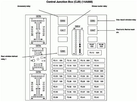
|
Fuse Number
|
Fuse Amperage
|
Fuse Function
|
|
1
|
20A
|
Powerpoint
|
|
2
|
30A
|
Handling powertrain control module
|
|
3
|
30A
|
Headlamps relay, main light switch, and multifunction switch
|
|
4
|
20A
|
Powerpoint for Harley Davidson Ford F150 Special Edition
|
|
5
|
20A
|
Park lamps and trailer tow backup
|
|
6
|
15A
|
Park lamp relay and main light switch
|
|
7
|
20A
|
The horn
|
|
8
|
15A
|
Power door locks, lock relays and CSM
|
|
9
|
15A
|
Daytime running lamps and fog lamps
|
|
10
|
20A
|
Fuel pump
|
|
11
|
20A
|
Alternator field
|
|
12
|
20A
|
Rear auxiliary powerpoint (Supercrew only)
|
|
13
|
15A
|
A/C clutch
|
|
14
|
|
Not in Use
|
|
15
|
10A
|
Running board lamps
|
|
16
|
15A
|
Alternative fuel injectors on Bi-fuel vehicles only, fuel selector switch, and bi-fuel injector module
|
|
17
|
|
Not in Use
|
|
18
|
15A
|
Mass airflow sensor, fuel injectors, PCM and fuel pump
|
|
19
|
10A
|
Right stop and right turn lamp trailer/camper adapter
|
|
20
|
10A
|
Left stop and right turn lamp trailer/camper adapter
|
|
21
|
|
Not in Use
|
|
22
|
|
Not in Use
|
|
23
|
15A
|
The heated exhaust gas oxygen sensor (HEGO) and automatic transmission
|
|
24
|
|
Not in Use
|
|
101
|
30A
|
Trailer tow battery charge
|
|
102
|
20A
|
4-wheel antilock brake module or rear wheel antilock brake module and ignition switch
|
|
103
|
50A
|
Central junction box
|
|
104
|
30A
|
4x4 shift motor and clutch
|
|
105
|
40A
|
Climate control front blower
|
|
106
|
20A
|
Intercooler pump on Supercharged engine only
|
|
107
|
|
Not in Use
|
|
108
|
30A
|
Trailer tow electric brake
|
|
109
|
|
Not in Use
|
|
110
|
30A
|
ACC delay relay
|
|
111
|
40A
|
Ignition switch for start and run circuits
|
|
112
|
30A
|
Drivers power seat and adjustable pedals
|
|
113
|
40A
|
Ignition switch battery feed
|
|
114
|
|
Not in Use
|
|
115
|
20A
|
Power door locks on SuperCrew only
|
|
116
|
40A
|
Heated backlight
|
|
117
|
30A
|
Audiophile radio on Supercrew only
|
|
118
|
30A
|
Heated Seats
|
|
Relay 201
|
|
Trailer tow park
|
|
Relay 202
|
|
Front wiper run/park
|
|
Relay 203
|
|
Trailer tow backup lamp
|
|
Relay 204
|
|
A/C clutch
|
|
Relay 205
|
|
Horn
|
|
Relay 206
|
|
Fog Lamp
|
|
Relay 207
|
|
Front washer pump
|
|
Relay 208
|
|
Intercooler pump for supercharged engines only
|
|
Relay 209
|
|
Front wiper lo/hi
|
|
Relay 301
|
|
Fuel pump
|
|
Relay 302
|
|
Trailer tow battery charge
|
|
Relay 303
|
|
Heated backlight relay Supercrew only
|
|
Relay 304
|
|
Powertrain control module (PCM)
|
|
Relay 305
|
|
Fuel pump hi/lo on supercharged engines only
|
|
Relay 306
|
|
Inertia Switch supercharged engines only
|
|
Relay 401
|
|
Not in Use
|
|
ATO Diode 501
|
|
PCM
|
|
ATO Diode 502
|
|
A/C compressor
|
|
ATO Diode 503
|
|
Not in Use
|
|
Circuit Breaker 601
|
|
SuperCrew power windows and moonroof
|
|
Fuse 602
|
|
Not in Use
|
You may note some subtle differences such as increases or decreases in amperage. There are some systems that have switched fuses and also some completely new systems that have been added.
There are several fuses that are only used in Ford F150 SuperCrews or trucks with a supercharger.
2004 Ford F150 Fuse Boxes Diagrams and Explanations
In the 2004 model year of the Ford F150 there were some big changes in the fuse boxes which will become clear as we go on to explain. There are still just two fuse boxes located in the same general areas of the truck.
What you will likely notice is that the Passenger Compartment Fuse Box has become more complex while the engine compartment box has become far more simplified.
Passenger Compartment Fuse Box

|
Fuse Number
|
Fuse Amperage
|
Fuse Function
|
|
1
|
10A
|
Cluster and run/accessory wipers
|
|
2
|
20A
|
Speed control deactivate switch and stop/turn lamps
|
|
3
|
5A
|
Pedals, memory seats, memory logic power and power mirrors
|
|
4
|
10A
|
DVD battery power
|
|
5
|
5A
|
Climate control and keeping alive memory for powertrain control module
|
|
6
|
15A
|
Instrument panel lighting, park lamps and BSM
|
|
7
|
5A
|
Radio start signal
|
|
8
|
10A
|
Heated mirrors and switch indicator
|
|
9
|
|
Not in Use
|
|
10
|
20A
|
Trailer tow park lamp and back up lamps relays
|
|
11
|
10A
|
A/C clutch and 4x4 solenoid
|
|
12
|
|
Not in Use
|
|
13
|
10A
|
Climate control module power
|
|
14
|
10A
|
Brake shift interlock solenoid, DRL relay coil, A/C pressure switch
|
|
15
|
5A
|
Cluster, brake shift interlock and overdrive cancel
|
|
16
|
10A
|
Run/Start power for ABS module
|
|
17
|
15A
|
Fog lamp relay
|
|
18
|
10A
|
Run/Start feed for flasher relay, heated seats, BSM, electrochromic mirror and compass
|
|
19
|
10A
|
Airbag module restraints
|
|
20
|
5A
|
Powertrain control module for 4x4 power
|
|
21
|
15A
|
Cluster keep alive power
|
|
22
|
10A
|
Moonroof switch illumination, power door lock switch, delayed accessory power for audio
|
|
23
|
10A
|
Right low beam headlamp
|
|
24
|
15A
|
Battery saver power for demand lamps
|
|
25
|
10A
|
Left low beam headlamp
|
|
26
|
20A
|
Horn power and relay
|
|
27
|
5A
|
PAD warning lamp, cluster airbag warning, cluster run/start power
|
|
28
|
5A
|
PATS SecuriLock transceiver
|
|
29
|
15A
|
PCM 4x4 power
|
|
30
|
|
Not in Use
|
|
31
|
20A
|
Radio power
|
|
32
|
15A
|
HEGO sensors #21 & #11, canister vent, A/C clutch relay, VCT, VMVand MAF
|
|
33
|
15A
|
CMS #22 and #12 and shift solenoid.
|
|
34
|
20A
|
PCM power and fuel injectors
|
|
35
|
20A
|
High beam headlamps, instrument cluster high beam indicator
|
|
36
|
10A
|
Trailer tow right stop/turn lamps
|
|
37
|
20A
|
Rear powerpoint
|
|
38
|
25A
|
Subwoofer power
|
|
39
|
20A
|
Instrument panel powerpoint
|
|
40
|
20A
|
DRL and low beam headlamps
|
|
41
|
20A
|
Diagnostic connector power and cigar lighter
|
|
42
|
20A
|
Trailer tow left stop/turn lamps
|
|
101
|
30A
|
Starter solenoid
|
|
102
|
20A
|
Ignition switch feed
|
|
103
|
20A
|
Anti-lock brake valves
|
|
104
|
|
Not in Use
|
|
105
|
30A
|
Electric trailer brakes
|
|
106
|
30A
|
Trailer tow battery charge
|
|
107
|
30A
|
BSM power door locks
|
|
108
|
30A
|
Passenger power seat
|
|
109
|
30A
|
Adjustable pedals and driver power seat
|
|
110
|
|
Not in Use
|
|
111
|
30A
|
4x4 Relays
|
|
112
|
40A
|
ABS pump power
|
|
113
|
30A
|
Washer pump and wipers
|
|
114
|
40A
|
Heated backlight and heated mirror power
|
|
115
|
|
Not in Use
|
|
116
|
30A
|
Blower motor
|
|
117
|
|
Not in Use
|
|
118
|
30A
|
Heated Seats
|
|
Circuit Breaker 401
|
30A
|
Power sliding backlight, moonroof, and power windows
|
|
Relay R01
|
|
Starter solenoid
|
|
Relay R02
|
|
Accessory delay
|
|
Relay R03
|
|
Hi-beam headlamps
|
|
Relay R04
|
|
Heated backlight
|
|
Relay R05
|
|
Trailer tow battery charge
|
|
Relay R06
|
|
Blower motor
|
|
Relay R201
|
|
Trailer tow park lamps
|
|
Relay R202
|
|
Fog Lamps
|
|
Relay R203
|
|
Powertrain control module (PCM)
|
Engine Compartment Box
This is no longer known as the Power Distribution Fuse Box but is still found in the same place as previous Ford F150 models. It is vastly less complicated than previous under hood fuse boxes.
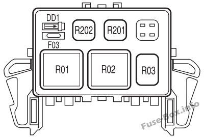
|
Fuse Number
|
Fuse Amperage
|
Fuse Function
|
|
F01
|
5A
|
Clock Spring Illumination
|
|
Relay R01
|
|
4x4 CCW
|
|
Relay R02
|
|
4x4 CW
|
|
Relay R03
|
|
Daytime running lights
|
|
Relay R201
|
|
Daytime running lights
|
|
Relay R202
|
|
A/C clutch
|
|
ATO Diode D01
|
|
A/C clutch
|
2005 Ford F150 Fuse Box Diagrams and Explanations
The fuse boxes in the 2005 Ford F150 are essentially the same as in the 2004 model but there are some differences which may be important when it comes to making repairs to your truck. Assuming a certain fuse that was for a specific function in 2004 is still the same could lead to issues.
Read on to see the updated information for the 2005 Ford F150 truck.
Passenger Compartment Fuse Box

|
Fuse Number
|
Fuse Amperage
|
Fuse Function
|
|
1
|
10A
|
Cluster and run/accessory wipers
|
|
2
|
20A
|
Speed control deactivate switch and stop/turn lamps
|
|
3
|
5A
|
Pedals, memory seats, memory logic power and power mirrors
|
|
4
|
10A
|
DVD battery power and power fold mirror
|
|
5
|
7.5A
|
Climate control and keeping alive memory for powertrain control module
|
|
6
|
15A
|
Instrument panel lighting, park lamps and BSM
|
|
7
|
5A
|
Radio start signal
|
|
8
|
10A
|
Heated mirrors and switch indicator
|
|
9
|
|
Not in Use
|
|
10
|
20A
|
Trailer tow park lamp and back up lamps relays
|
|
11
|
10A
|
A/C clutch and 4x4 solenoid
|
|
12
|
|
Not in Use
|
|
13
|
10A
|
Climate control module power and flasher relay
|
|
14
|
10A
|
ABS, heated PCV 5.4L, backup lamp, reverse park aid, EC mirror, DRL relay, trailer tow back up light, redundant speed control A/C pressure switch
|
|
15
|
5A
|
Cluster, brake shift interlock and overdrive cancel
|
|
16
|
10A
|
Brake shift interlock solenoid
|
|
17
|
15A
|
Fog lamp relay
|
|
18
|
10A
|
Run/Start feed for overhead powerpoint, RSS, heated seats, BSM, electrochromic mirror and compass
|
|
19
|
10A
|
Airbag module restraints
|
|
20
|
10A
|
Overhead powerpoint battery feed
|
|
21
|
15A
|
Cluster keep alive power
|
|
22
|
10A
|
Moonroof switch illumination, power door lock switch, delayed accessory power for audio
|
|
23
|
10A
|
Right low beam headlamp
|
|
24
|
15A
|
Battery saver power for demand lamps
|
|
25
|
10A
|
Left low beam headlamp
|
|
26
|
20A
|
Horn power and relay
|
|
27
|
5A
|
PAD warning lamp, cluster airbag warning, cluster run/start power
|
|
28
|
5A
|
PATS SecuriLock transceiver
|
|
29
|
15A
|
PCM 4x4 power
|
|
30
|
15A
|
PCM 4×4 power
|
|
31
|
20A
|
Radio power
|
|
32
|
15A
|
HEGO sensors #21 & #11, canister vent, A/C clutch relay, VCT, VMV, CMCV, heated PCV valve 4.2L engine, CID sensor 4.2L engine and MAF
|
|
33
|
15A
|
CMS #22 and #12 and shift solenoid.
|
|
34
|
20A
|
PCM power, 4.2L engine intake manifold runner control, and fuel injectors
|
|
35
|
20A
|
High beam headlamps, instrument cluster high beam indicator
|
|
36
|
10A
|
Trailer tow right stop/turn lamps
|
|
37
|
20A
|
Rear powerpoint
|
|
38
|
25A
|
Subwoofer power
|
|
39
|
20A
|
Instrument panel powerpoint
|
|
40
|
20A
|
DRL and low beam headlamps
|
|
41
|
20A
|
Diagnostic connector power and cigar lighter
|
|
42
|
20A
|
Trailer tow left stop/turn lamps
|
|
101
|
30A
|
Starter solenoid
|
|
102
|
20A
|
Ignition switch feed
|
|
103
|
20A
|
Anti-lock brake valves
|
|
104
|
|
Not in Use
|
|
105
|
30A
|
Electric trailer brakes
|
|
106
|
30A
|
Trailer tow battery charge
|
|
107
|
30A
|
BSM power door locks
|
|
108
|
30A
|
Passenger power seat
|
|
109
|
30A
|
Adjustable pedals and driver power seat
|
|
110
|
|
Not in Use
|
|
111
|
30A
|
4x4 Relays
|
|
112
|
40A
|
ABS pump power
|
|
113
|
30A
|
Washer pump and wipers
|
|
114
|
40A
|
Heated backlight and heated mirror power
|
|
115
|
|
Not in Use
|
|
116
|
30A
|
Blower motor
|
|
117
|
|
Not in Use
|
|
118
|
30A
|
Heated Seats
|
|
Circuit Breaker 401
|
30A
|
Power sliding backlight, moonroof, and power windows
|
|
Relay R01
|
|
Starter solenoid
|
|
Relay R02
|
|
Accessory delay
|
|
Relay R03
|
|
Hi-beam headlamps
|
|
Relay R04
|
|
Heated backlight
|
|
Relay R05
|
|
Trailer tow battery charge
|
|
Relay R06
|
|
Blower motor
|
|
Relay R201
|
|
Trailer tow park lamps
|
|
Relay R202
|
|
Fog Lamps
|
|
Relay R203
|
|
Powertrain control module (PCM)
|
Engine Compartment Fuse Box
In the 2005 Ford F150 there are no notable changes in the engine compartment fuse box
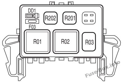
|
Fuse Number
|
Fuse Amperage
|
Fuse Function
|
|
F01
|
5A
|
Clock Spring Illumination
|
|
Relay R01
|
|
4x4 CCW
|
|
Relay R02
|
|
4x4 CW
|
|
Relay R03
|
|
Daytime running lights
|
|
Relay R201
|
|
Daytime running lights
|
|
Relay R202
|
|
A/C clutch
|
|
ATO Diode D01
|
|
A/C clutch
|
2006 Ford F150 Fuse Box Diagram and Explanations
We are still able to compare the fuse boxes from the 2006 Ford F150 trucks to those found in the 2004 model year but there are some definite changes when it comes to some of the fuses’ functions. As before, be mindful to check for changes as this is important so you know you are pulling the correct fuses.
Passenger Compartment Fuse Box

|
Fuse Number
|
Fuse Amperage
|
Fuse Function
|
|
1
|
10A
|
Instrument cluster XL/STX audio run/accessory wipers
|
|
2
|
20A
|
Brake on/off switch switch and stop/turn lamps
|
|
3
|
7.5A
|
Pedals, memory seats and power mirrors
|
|
4
|
10A
|
DVD battery power and power fold mirrors
|
|
5
|
7.s5A
|
Climate control and keeping alive memory for powertrain control module
|
|
6
|
15A
|
Instrument panel lighting, park lamps and BSM
|
|
7
|
5A
|
Radio start signal
|
|
8
|
10A
|
Heated mirrors and switch indicator
|
|
9
|
20A
|
Intake manifold runner control 4.2L, fuel pump relay, and fuel injectors
|
|
10
|
20A
|
Trailer tow park lamp and back up lamps relays
|
|
11
|
10A
|
A/C clutch and 4x4 solenoid
|
|
12
|
5A
|
Powertrain control module relay coil
|
|
13
|
10A
|
Climate control module power and flasher relay
|
|
14
|
10A
|
Brake shift interlock solenoid, DRL relay coil, trailer tow back-up lamps relay coil, reverse park aid, EC mirror, A/C pressure switch and redundant speed control switch
|
|
15
|
5A
|
Cluster, and overdrive cancel
|
|
16
|
10A
|
Brake shift interlock solenoid
|
|
17
|
15A
|
Fog lamp relay
|
|
18
|
10A
|
Run/Start feed for flasher relay, RSS, overhead powerpoint, heated seats, BSM, electrochromic mirror and compass
|
|
19
|
10A
|
Airbag module restraints
|
|
20
|
10A
|
Overhead powerpoint battery feed
|
|
21
|
15A
|
Cluster keep alive power
|
|
22
|
10A
|
Moonroof switch illumination, power door lock switch, delayed accessory power for audio
|
|
23
|
10A
|
Right low beam headlamp
|
|
24
|
15A
|
Battery saver power for demand lamps
|
|
25
|
10A
|
Left low beam headlamp
|
|
26
|
20A
|
Horn power and relay
|
|
27
|
5A
|
PAD warning lamp, cluster airbag warning, cluster run/start power
|
|
28
|
5A
|
PATS SecuriLock transceiver and PCM IGN monitor
|
|
29
|
15A
|
PCM 4x4 power
|
|
30
|
15A
|
PCM 4x4 power
|
|
31
|
20A
|
Radio power
|
|
32
|
15A
|
HEGO sensors #21 & #11, canister vent, A/C clutch relay, VCT, VMV, heated PCV valve 4.2L engine, CID sensor 4.2L engine, and 4.6L/4.2L EGR and MAF
|
|
33
|
15A
|
CMS #22 and #12, ignition coils and shift solenoid
|
|
34
|
20A
|
PCM power
|
|
35
|
20A
|
High beam headlamps, instrument cluster high beam indicator
|
|
36
|
10A
|
Trailer tow right stop/turn lamps
|
|
37
|
20A
|
Rear powerpoint
|
|
38
|
25A
|
Subwoofer power
|
|
39
|
20A
|
Instrument panel powerpoint
|
|
40
|
20A
|
DRL and low beam headlamps
|
|
41
|
20A
|
Diagnostic connector power and cigar lighter
|
|
42
|
20A
|
Trailer tow left stop/turn lamps
|
|
101
|
30A
|
Starter solenoid
|
|
102
|
20A
|
Ignition switch feed
|
|
103
|
20A
|
Anti-lock brake valves
|
|
104
|
|
Not in Use
|
|
105
|
30A
|
Electric trailer brakes
|
|
106
|
30A
|
Trailer tow battery charge
|
|
107
|
30A
|
BSM power door locks
|
|
108
|
30A
|
Passenger power seat
|
|
109
|
30A
|
Adjustable pedals and driver power seat
|
|
110
|
|
Not in Use
|
|
111
|
30A
|
4x4 Relays
|
|
112
|
40A
|
ABS pump power
|
|
113
|
30A
|
Washer pump and wipers
|
|
114
|
40A
|
Heated backlight and heated mirror power
|
|
115
|
|
Not in Use
|
|
116
|
30A
|
Blower motor
|
|
117
|
|
Not in Use
|
|
118
|
30A
|
Heated Seats
|
|
Circuit Breaker 401
|
30A
|
Power sliding backlight, moonroof, and power windows
|
|
Relay R01
|
|
Starter solenoid
|
|
Relay R02
|
|
Accessory delay
|
|
Relay R03
|
|
Hi-beam headlamps
|
|
Relay R04
|
|
Heated backlight
|
|
Relay R05
|
|
Trailer tow battery charge
|
|
Relay R06
|
|
Blower motor
|
|
Relay R201
|
|
Trailer tow park lamps
|
|
Relay R202
|
|
Fog Lamps
|
|
Relay R203
|
|
Powertrain control module (PCM)
|
Engine Compartment Fuse Box
The 2006 Ford F150 engine compartment box is slightly altered from the 2004 version so read on to see those changes.

|
Fuse Number
|
Fuse Amperage
|
Fuse Function
|
|
F03
|
5A
|
Clock Spring Illumination
|
|
Relay R01
|
|
4x4 CCW
|
|
Relay R02
|
|
4x4 CW
|
|
Relay R03
|
|
Disabling daytime running lights high beam
|
|
Relay R201
|
|
Daytime running lights
|
|
Relay R202
|
|
A/C clutch
|
|
ATO Diode D01
|
|
A/C clutch
|
2007 Ford F150 Fuse Box Diagram and Explanation
We will have a consistent fuse box layout as compared with the 2004 Ford F150 but with definite changes to some of the fuse functions. As always the passenger and engine bay fuse boxes can be found in the same places they have been since 1999.
Passenger Compartment Fuse Box

|
Fuse Number
|
Fuse Amperage
|
Fuse Function
|
|
1
|
10A
|
Instrument cluster, XL/STX audio, run/accessory wipers
|
|
2
|
20A
|
Brake on/off switch, hazard flashers, and stop/turn lamps
|
|
3
|
7.5A
|
Pedals, memory seats, power seats and power mirrors
|
|
4
|
10A
|
DVD battery power and power-fold mirror
|
|
5
|
7.5A
|
Climate control and keeping alive memory for powertrain control module
|
|
6
|
15A
|
Instrument panel lighting, park lamps and BSM
|
|
7
|
5A
|
Radio start signal
|
|
8
|
10A
|
Heated mirrors and switch indicator
|
|
9
|
20A
|
Intake manifold runner control 4.2L, fuel pump relay, and fuel injectors
|
|
10
|
20A
|
Trailer tow park lamp and back up lamps relays
|
|
11
|
10A
|
A/C clutch and 4x4 solenoid
|
|
12
|
5A
|
Powertrain control module relay coil
|
|
13
|
10A
|
Climate control module power and flasher relay
|
|
14
|
10A
|
Anti-lock brake system,, Heated PCV 5.4L, redundant speed control switch, back-up lamp, and DRL relay coil, A/C pressure switch, trailer tow back-up lamps relay coil, reverse park aid, EC mirror, reverse input navigation radio
|
|
15
|
5A
|
Cluster, traction control switch and overdrive cancel
|
|
16
|
10A
|
Brake shift interlock solenoid
|
|
17
|
15A
|
Fog lamp relay
|
|
18
|
10A
|
Run/Start feed for flasher relay, RSS, overhead powerpoint, heated seats, BSM, electrochromic mirror and compass
|
|
19
|
10A
|
Airbag module restraints and OCS
|
|
20
|
10A
|
Overhead powerpoint battery feed
|
|
21
|
15A
|
Cluster keep alive power
|
|
22
|
10A
|
Moonroof switch illumination, power door lock switch, delayed accessory power for audio
|
|
23
|
10A
|
Right low beam headlamp
|
|
24
|
15A
|
Battery saver power for demand lamps
|
|
25
|
10A
|
Left low beam headlamp
|
|
26
|
20A
|
Horn power and relay
|
|
27
|
5A
|
PAD warning lamp and cluster run/start power
|
|
28
|
5A
|
PATS SecuriLock transceiver and PCM IGN monitor
|
|
29
|
15A
|
PCM 4x4 power
|
|
30
|
15A
|
PCM 4x4 power
|
|
31
|
20A
|
Radio power and satellite radio module
|
|
32
|
15A
|
HEGO sensors #21 & #11, canister vent, CMCV A/C clutch relay, VCT, VMV, heated PCV valve 4.2L engine, CID sensor 4.2L engine and 4.6L/4.2L EGR and MAF
|
|
33
|
15A
|
CMS #22 and #12 and ignition coils
|
|
34
|
15A
|
PCM power
|
|
35
|
20A
|
High beam headlamps, instrument cluster high beam indicator
|
|
36
|
10A
|
Trailer tow right stop/turn lamps
|
|
37
|
20A
|
Rear powerpoint and center console powerpoint
|
|
38
|
25A
|
Subwoofer power
|
|
39
|
20A
|
Instrument panel powerpoint
|
|
40
|
20A
|
DRL and low beam headlamps
|
|
41
|
20A
|
Diagnostic connector power and cigar lighter
|
|
42
|
10A
|
Trailer tow left stop/turn lamps
|
|
101
|
30A
|
Starter solenoid
|
|
102
|
20A
|
Ignition switch feed
|
|
103
|
20A
|
Anti-lock brake valves
|
|
104
|
|
Not in Use
|
|
105
|
30A
|
Electric trailer brakes
|
|
106
|
30A
|
Trailer tow battery charge
|
|
107
|
30A
|
BSM power door locks
|
|
108
|
30A
|
Passenger power seat
|
|
109
|
30A
|
Adjustable pedals, memory module (mirror, pedals, seats) and driver power seat
|
|
110
|
|
Not in Use
|
|
111
|
30A
|
4x4 Relays
|
|
112
|
40A
|
ABS pump power
|
|
113
|
30A
|
Washer pump and wipers
|
|
114
|
40A
|
Heated backlight and heated mirror power
|
|
115
|
20A
|
Spare fuse not in use
|
|
116
|
30A
|
Blower motor
|
|
117
|
|
Not in Use
|
|
118
|
30A
|
Heated Seats
|
|
Circuit Breaker 401
|
30A
|
Power sliding backlight, moonroof, and delayed accessory power: power windows
|
|
Relay R01
|
|
Starter solenoid
|
|
Relay R02
|
|
Accessory delay
|
|
Relay R03
|
|
Hi-beam headlamps
|
|
Relay R04
|
|
Heated backlight
|
|
Relay R05
|
|
Trailer tow battery charge
|
|
Relay R06
|
|
Blower motor
|
|
Relay R201
|
|
Trailer tow park lamps
|
|
Relay R202
|
|
Fog Lamps
|
|
Relay R203
|
|
Powertrain control module (PCM)
|
Engine Compartment Fuse box
The changes from the 2006 Ford F150 engine compartment fuse box are the same as found in the 2007 version.
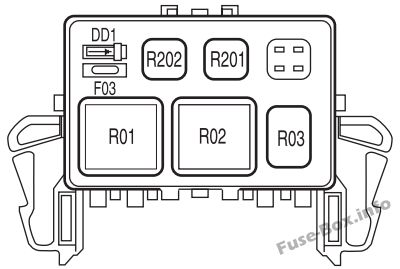
|
Fuse Number
|
Fuse Amperage
|
Fuse Function
|
|
F03
|
5A
|
Clock Spring Illumination
|
|
Relay R01
|
|
4x4 CCW
|
|
Relay R02
|
|
4x4 CW
|
|
Relay R03
|
|
Disabling daytime running lights high beam
|
|
Relay R201
|
|
Daytime running lights
|
|
Relay R202
|
|
A/C clutch
|
|
ATO Diode D01
|
|
A/C clutch
|
2008 Ford F150 Fuse Box Diagram and Explanation
The 2008 Ford F150 fuse box sees a lot of changes when it comes to fuse functions but is essentially the same layout as in previous years.
Passenger Compartment Fuse Box

|
Fuse Number
|
Fuse Amperage
|
Fuse Function
|
|
1
|
10A
|
Instrument cluster, XL/STX audio, and run/accessory wipers
|
|
2
|
20A
|
Anti-lock brake system, CHMSL, PCM, T/T electric brake module, turn signal mirrors, and stop/turn lamps
|
|
3
|
5A
|
Pedals, memory seats, and power mirrors
|
|
4
|
10A
|
DVD battery power power-fold mirror
|
|
5
|
5A
|
Climate control and keeping alive memory for powertrain control module
|
|
6
|
15A
|
Instrument panel lighting, park lamps and BSM
|
|
7
|
5A
|
Radio start signal
|
|
8
|
10A
|
Heated mirrors and switch indicator
|
|
9
|
20A
|
Injector sense, fuel pump relay, and fuel injectors
|
|
10
|
20A
|
Trailer tow park lamp and back up lamps relays
|
|
11
|
10A
|
A/C clutch and 4x4 solenoid
|
|
12
|
5A
|
PCM relay coil
|
|
13
|
10A
|
Climate control module power and flasher relay
|
|
14
|
10A
|
ABS, Heated PCV 5.4L, redundant speed control switch, backup lamp and DRL relay coil, A/C pressure switch
|
|
15
|
5A
|
Cluster and overdrive cancel
|
|
16
|
10A
|
Brake shift interlock solenoid
|
|
17
|
15A
|
Fog lamp relay
|
|
18
|
10A
|
RSS, heated seats, BSM, electrochromic mirror, power rail, and compass
|
|
19
|
10A
|
Airbag module restraints
|
|
20
|
10A
|
Power rail
|
|
21
|
15A
|
Cluster keep alive power
|
|
22
|
10A
|
Moonroof switch illumination, power door lock switch, delayed accessory power for audio
|
|
23
|
10A
|
Right low beam headlamp
|
|
24
|
15A
|
Battery saver power for demand lamps and flex-fuel
|
|
25
|
10A
|
Left low beam headlamp
|
|
26
|
20A
|
Truck horn
|
|
27
|
5A
|
PAD warning lamp and cluster airbag warning
|
|
28
|
5A
|
PATS SecuriLock transceiver and PCM IGN monitor
|
|
29
|
15A
|
PCM 4x4 power
|
|
30
|
15A
|
Powertrain control module 4x4 power
|
|
31
|
20A
|
Radio power and satellite radio module
|
|
32
|
15A
|
HEGO sensors #21 & #11, canister vent, heated PCV valve 4.2L engine, CID sensor 4.2L engine, and 4.6L/4.2L EGR A/C clutch relay, VCT, VMV, CMCV and MAF
|
|
33
|
15A
|
Ignition coils, CMS #22 and #12 and shift solenoid.
|
|
34
|
20A
|
PCM power and 4.2L IMRC
|
|
35
|
20A
|
High beam headlamps, instrument cluster high beam indicator and DRL display ray
|
|
36
|
10A
|
Trailer tow right stop/turn lamps
|
|
37
|
20A
|
Rear powerpoint
|
|
38
|
25A
|
Subwoofer power
|
|
39
|
|
Not in Use
|
|
40
|
20A
|
DRL and low beam headlamps
|
|
41
|
|
Not in Use
|
|
42
|
10A
|
Trailer tow left stop/turn lamps
|
|
101
|
30A
|
Starter solenoid
|
|
102
|
20A
|
Ignition switch feed
|
|
103
|
20A
|
Anti-lock brake valves
|
|
104
|
|
Not in Use
|
|
105
|
30A
|
Electric trailer brakes
|
|
106
|
30A
|
Trailer tow battery charge
|
|
107
|
30A
|
BSM power door locks
|
|
108
|
30A
|
Passenger power seat
|
|
109
|
30A
|
Adjustable pedals, memory modules and driver power seat
|
|
110
|
20A
|
Diagnostic connector power and cigar lighter
|
|
111
|
30A
|
4x4 motor relays
|
|
112
|
40A
|
ABS pump power
|
|
113
|
30A
|
Washer pump and wipers
|
|
114
|
40A
|
Heated backlight and heated mirror power
|
|
115
|
20A
|
Moonroof
|
|
116
|
30A
|
Blower motor
|
|
117
|
20A
|
Instrument panel powerpoint
|
|
118
|
30A
|
Heated Seats
|
|
Circuit Breaker 401
|
30A
|
Power sliding backlight, moonroof, and power windows
|
|
Relay R01
|
|
Starter solenoid
|
|
Relay R02
|
|
Accessory delay
|
|
Relay R03
|
|
Hi-beam headlamps
|
|
Relay R04
|
|
Heated backlight
|
|
Relay R05
|
|
Trailer tow battery charge
|
|
Relay R06
|
|
Blower motor
|
|
Relay R201
|
|
Trailer tow park lamps
|
|
Relay R202
|
|
Fog Lamps
|
|
Relay R203
|
|
Powertrain control module (PCM)
|
|
Relay R301
|
|
Printed circuit board trailer tow backup lamps.
|
|
Relay R302
|
|
Not in Use
|
|
Relay R303
|
|
Printed circuit board fuel pump
|
|
Relay R304
|
|
Printed circuit board battery saver
|
|
Relay R305
|
|
Printed circuit board horn
|
Engine Compartment Fuse Box
|
Fuse Number
|
Fuse Amperage
|
Fuse Function
|
|
F03
|
5A
|
Clock Spring Illumination
|
|
Relay R01
|
|
4x4 CCW
|
|
Relay R02
|
|
4x4 CW
|
|
Relay R03
|
|
Disabling daytime running lights high beam
|
|
Relay R201
|
|
Daytime running lights
|
|
Relay R202
|
|
A/C clutch
|
|
ATO Diode D01
|
|
A/C clutch
|
|
ATO Diode D02
|
|
One Touch Integrated Start (OTIS)
|
2009 Ford F150 Fuse Box Diagrams and Explanations
In 2009 there was another overhaul of the fuse boxes for the Ford F150 line which led to some major changes. The Power Distribution Fuse Box returns and once again is a complex collection of fuses and relays.
Passenger Compartment Fuse Box
The Passenger Compartment Fuse Box as in previous years can be found behind a protective panel near the brake pedal below the steering wheel. Removing this panel will allow you access to a large bank of fuses.
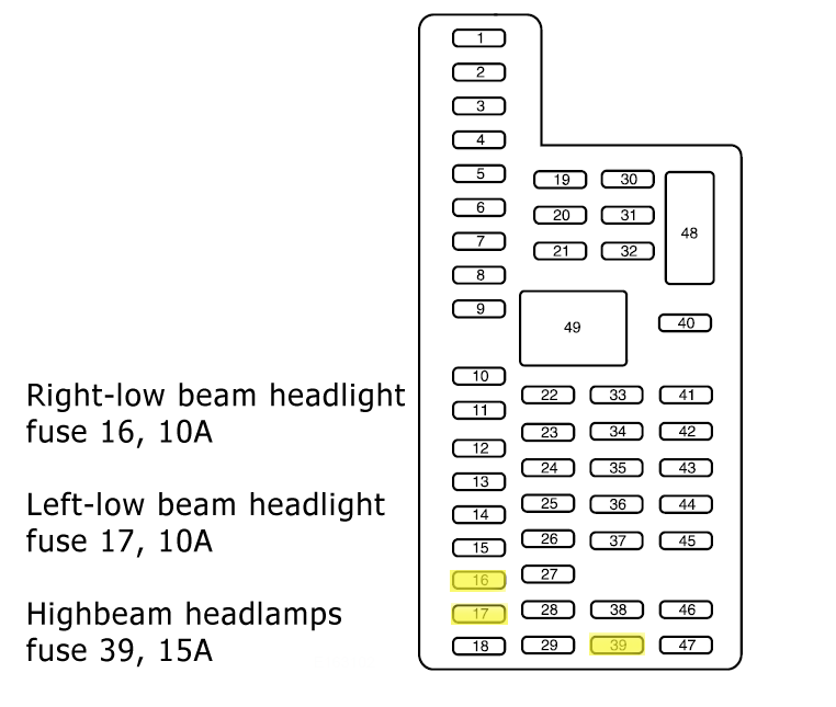
|
Fuse Number
|
Fuse Amperage
|
Fuse Function
|
|
1
|
30A
|
Moonroof
|
|
2
|
15A
|
Spare but not in use
|
|
3
|
15A
|
Spare but not in use
|
|
4
|
15A
|
Spare but not in use
|
|
5
|
10A
|
SJB microprocessor, keypad illumination and brake shift interlock
|
|
6
|
20A
|
Stop lamps and turn signals
|
|
7
|
10A
|
Left low beam headlamps
|
|
8
|
10A
|
Right low beam headlamps
|
|
9
|
15A
|
Cargo lamps and interior courtesy lights
|
|
10
|
15A
|
Puddle lamps and backlighting
|
|
11
|
10A
|
Spare but not in use
|
|
12
|
7.5A
|
Memory seat module microprocessor power, steering column switch and power mirror switch
|
|
13
|
5A
|
FOR sync
|
|
14
|
10A
|
Spare but not in use
|
|
15
|
10A
|
Climate Control
|
|
16
|
15A
|
Ignition switch feed
|
|
17
|
20A
|
Lock motor feeds
|
|
18
|
20A
|
Driver memory seat switch
|
|
19
|
25A
|
Spare but not in use
|
|
20
|
15A
|
Datalink and adjustable pedals
|
|
21
|
15A
|
Fog lamp indicator and fog lamps
|
|
22
|
15A
|
Park lamps and side marker lamps
|
|
23
|
15A
|
High beam headlamps
|
|
24
|
20A
|
Horn
|
|
25
|
10A
|
Interior demand lamps and mid box power feed
|
|
26
|
10A
|
Radio buttons, CID radio info display, key-in chime, key-out inhibit solenoid and instrumental panel cluster
|
|
27
|
20A
|
Not in Use
|
|
28
|
5A
|
Radio muting
|
|
29
|
5A
|
Instrument panel cluster
|
|
30
|
5A
|
Passenger airbag disable indicator
|
|
31
|
10A
|
Restraints control module
|
|
32
|
10A
|
Non-integrated compass module and heated only seat module
|
|
33
|
10A
|
Trailer brake controller
|
|
34
|
5A
|
Electronic locking differential indicator
|
|
35
|
10A
|
Rear park assist
|
|
36
|
5A
|
PATS transceiver
|
|
37
|
10A
|
Spare but not in use
|
|
38
|
20A
|
Subwoofer
|
|
39
|
20A
|
Navigation display and radio
|
|
40
|
20A
|
Spare but not in use
|
|
41
|
15A
|
Electrochromic mirror lock switch illumination and radio accessory delay
|
|
42
|
10A
|
Spare but not in use
|
|
43
|
10A
|
Heated mirror/backlight relay, rain sensor and reverse camera
|
|
44
|
10A
|
Spare but not in use
|
|
45
|
5A
|
Blower motor relay and front wiper logic
|
|
46
|
7.5A
|
Occupant classification Sensor (OCS)
|
|
Circuit Breaker 47
|
30A
|
Power sliding backlight, power windows and moonroof
|
|
Relay 48
|
|
Delayed accessory delay for circuit breaker #47 and feeds fuse #41
|
You will likely note that there are several spare fuses in the circuit of various amps which can be used as replacements as and when needed.
Power Distribution Fuse Box
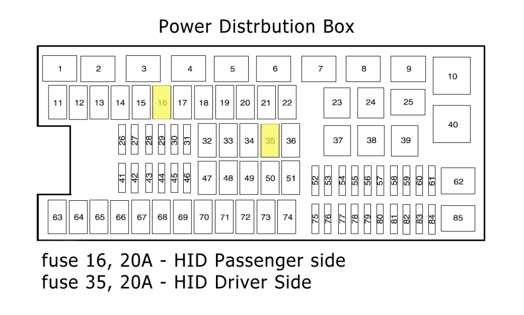
|
Fuse Number
|
Fuse Amperage
|
Fuse Function
|
|
Relay 1
|
|
Powertrain control module
|
|
Relay 2
|
|
Starter
|
|
Relay 3
|
|
Blower motor
|
|
Relay 4
|
|
Heated backlite
|
|
Relay 5
|
|
Not in Use
|
|
Relay 6
|
|
Trailer tow park lamp
|
|
Relay 7
|
|
Not in Use
|
|
Relay 8
|
|
Fuel Pump
|
|
Relay 9
|
|
Trailer tow battery charger
|
|
Relay 10
|
|
Not in Use
|
|
11
|
30A
|
Power running board motors
|
|
12
|
|
Not in Use
|
|
13
|
30A
|
Starter relay
|
|
14
|
30A
|
Passenger power seats
|
|
15
|
|
Not in Use
|
|
16
|
|
Not in Use
|
|
17
|
30A
|
Trailer brake
|
|
18
|
|
Not in Use
|
|
19
|
|
Not in Use
|
|
20
|
20A
|
Electric Shift On the Fly (ESOF) 4x4 module
|
|
21
|
30A
|
Trailer to the battery charge
|
|
22
|
20A
|
Cigarette lighter
|
|
23
|
20A
|
A/C clutch relay
|
|
Relay 24
|
|
Not in Use
|
|
Relay 25
|
|
Not in Use
|
|
26
|
10A
|
Powertrain control module relay, transmission, keep alive power PCM and canister vent solenoid
|
|
27
|
20A
|
Fuel pump relay
|
|
28
|
|
Not in Use
|
|
29
|
10A
|
4x4
|
|
30
|
10A
|
A/C clutch
|
|
31
|
20A
|
Trailer tow park lamp relay
|
|
32
|
40A
|
Mirror relay/heated backlite
|
|
33
|
|
Not in Use
|
|
34
|
40A
|
PCM relay
|
|
35
|
|
Not in Use
|
|
36
|
30A
|
Roll stability control module
|
|
Relay 37
|
|
Trailer tow left-hand stop or turn
|
|
Relay 38
|
|
Trailer tow right-hand stop or turn
|
|
Relay 39
|
|
Backup lamps
|
|
Relay 40
|
|
Not in Use
|
|
41
|
|
Not in Use
|
|
42
|
|
Not in Use
|
|
43
|
20A
|
Backup lamp relay
|
|
44
|
|
Not in Use
|
|
45
|
20A
|
Trailer tow stop turn relay feed
|
|
46
|
15A
|
Brake on/off switch
|
|
47
|
60A
|
Roll stability control module
|
|
48
|
|
Not in Use
|
|
49
|
30A
|
Wiper motor and washer pump
|
|
50
|
|
Not in Use
|
|
51
|
40A
|
Blower motor relay
|
|
52
|
|
Not in Use
|
|
53
|
5A
|
PCM and 6R80 transmission
|
|
54
|
5A
|
Backup lamp, 4x4 module, trailer tow battery charge relay and roll stability control
|
|
55
|
5A
|
6R transmissions only electronic compass mirror
|
|
56
|
|
Not in Use
|
|
57
|
|
Not in Use
|
|
58
|
15A
|
Trailer tow backup lamps
|
|
59
|
15A
|
Heated mirrors
|
|
Diode 60
|
|
One touch start
|
|
Diode 61
|
|
Fuel pump
|
|
Relay 62
|
|
Not in Use
|
|
63
|
|
Not in Use
|
|
64
|
30A
|
Amplifier
|
|
65
|
20A
|
Auxiliary power point instrument panel
|
|
66
|
20A
|
Auxiliary powerpoint inside the center console
|
|
67
|
|
Not in Use
|
|
68
|
20A
|
4x4 module
|
|
69
|
30A
|
Passenger cooled/heated seats
|
|
70
|
|
Not in Use
|
|
71
|
|
Not in Use
|
|
72
|
20A
|
Rear auxiliary powerpoint
|
|
73
|
|
Not in Use
|
|
74
|
30A
|
Driver Power seat
|
|
75
|
15A
|
PCM – Vehicle Power 1 (VPWR1)
|
|
76
|
20A
|
Brake on/off, VPWR2, CMS #12 and #22, MAF/IAT, VBV with 6R80 transmission
|
|
77
|
10A
|
Electric fan clutch, A/C clutch relay coil, 4-speed transmission floor shifter and VPWR3
|
|
78
|
25A
|
Ignition coils and VPWR4
|
|
79
|
10A
|
CMS and #12 & #22 with 4-speed transmission
|
|
80
|
5A
|
Steering wheel illumination
|
|
81
|
|
Not in Use
|
|
82
|
10A
|
Traction brake control module, aftermarket CHMSL and center high mount brake lamp
|
|
83
|
|
Not in Use
|
|
84
|
|
A/C clutch
|
|
Relay 85
|
|
Not in Use
|
You will likely notice there are a lot of relays and fuses that are not in use. This means that additions can be made to the Ford F150 over the following years.
2010 Ford F150 Fuse Box Diagram and Explanation
The 2010 Ford F150 fuse boxes have the same layout as the 2009 model year and can be found in the same places. There have been several notable changes in the functions of some of these fuses and relays.
Passenger Compartment Fuse Box
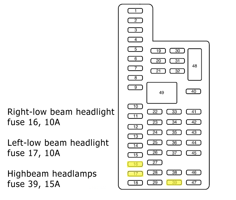
|
Fuse Number
|
Fuse Amperage
|
Fuse Function
|
|
1
|
30A
|
Moonroof
|
|
2
|
15A
|
Spare but not in use
|
|
3
|
15A
|
Spare but not in use
|
|
4
|
30A
|
Spare but not in use
|
|
5
|
10A
|
SJB microprocessor, keypad illumination and brake shift interlock
|
|
6
|
20A
|
Stop lamps and turn signals
|
|
7
|
10A
|
Left low beam headlamps
|
|
8
|
10A
|
Right low beam headlamps
|
|
9
|
15A
|
Cargo lamps and interior courtesy lights
|
|
10
|
15A
|
Puddle lamps and backlighting
|
|
11
|
10A
|
GPS module
|
|
12
|
7.5A
|
Memory seat module microprocessor power, steering column switch and power mirror switch
|
|
13
|
5A
|
FOR sync
|
|
14
|
10A
|
Ambient lighting module
|
|
15
|
10A
|
Climate Control
|
|
16
|
15A
|
Ignition switch feed
|
|
17
|
20A
|
Lock motor feeds
|
|
18
|
20A
|
Driver memory seat switch
|
|
19
|
25A
|
Spare but not in use
|
|
20
|
15A
|
Datalink and adjustable pedals
|
|
21
|
15A
|
Fog lamp indicator and fog lamps
|
|
22
|
15A
|
Park lamps and side marker lamps
|
|
23
|
15A
|
High beam headlamps
|
|
24
|
20A
|
Horn
|
|
25
|
10A
|
Interior demand lamps and mid box power feed
|
|
26
|
10A
|
Radio buttons, CID radio info display, key-in chime, key-out inhibit solenoid and instrumental panel cluster
|
|
27
|
20A
|
Not in Use
|
|
28
|
5A
|
Radio muting
|
|
29
|
5A
|
Instrument panel cluster
|
|
30
|
5A
|
Passenger airbag disable indicator
|
|
31
|
10A
|
Restraints control module
|
|
32
|
10A
|
Non-integrated compass module and heated only seat module
|
|
33
|
10A
|
Trailer brake controller
|
|
34
|
5A
|
Electronic locking differential indicator
|
|
35
|
10A
|
Rear park assist
|
|
36
|
5A
|
PATS transceiver
|
|
37
|
10A
|
Upfitter relay coils
|
|
38
|
20A
|
Subwoofer
|
|
39
|
20A
|
Navigation display and radio
|
|
40
|
20A
|
Rear heated seat module
|
|
41
|
15A
|
Radio accessory delay, door lock switch illumination, auto-dimming rearview mirror
|
|
42
|
10A
|
Spare but not in use
|
|
43
|
10A
|
Heated mirror/backlight relay, rain sensor and reverse camera
|
|
44
|
10A
|
Spare but not in use
|
|
45
|
5A
|
Blower motor relay and front wiper logic
|
|
46
|
7.5A
|
Occupant classification Sensor (OCS)
|
|
Circuit Breaker 47
|
30A
|
Power sliding backlight, power windows and moonroof
|
|
Relay 48
|
|
Delayed accessory delay for circuit breaker #47 and feeds fuse #41
|
Power Distribution Box
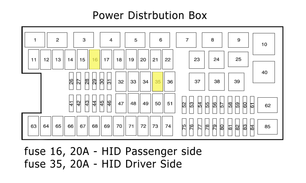
|
Fuse Number
|
Fuse Amperage
|
Fuse Function
|
|
Relay 1
|
|
Powertrain control module
|
|
Relay 2
|
|
Starter
|
|
Relay 3
|
|
Blower motor
|
|
Relay 4
|
|
Heated backlite
|
|
Relay 5
|
|
High-speed electric fan speed
|
|
Relay 6
|
|
Trailer tow park lamp
|
|
Relay 7
|
|
Upfitter 1
|
|
Relay 8
|
|
Fuel Pump
|
|
Relay 9
|
|
Trailer tow battery charger
|
|
Relay 10
|
|
Upfitter 2
|
|
11
|
30A
|
Power running board motors
|
|
12
|
40A
|
Electric fan
|
|
13
|
30A
|
Starter relay
|
|
14
|
30A
|
Passenger power seats
|
|
15
|
40A
|
Electric fan
|
|
16
|
|
Not in Use
|
|
17
|
30A
|
Trailer brake
|
|
18
|
30A
|
Upfitter 1
|
|
19
|
30A
|
Upfitter 2
|
|
20
|
20A
|
Electric Shift On the Fly (ESOF) 4x4 module
|
|
21
|
30A
|
Trailer to the battery charge
|
|
22
|
20A
|
Cigarette lighter
|
|
23
|
20A
|
A/C clutch relay
|
|
Relay 24
|
|
Upfitter 4
|
|
Relay 25
|
|
Heated mirror
|
|
26
|
10A
|
Powertrain control module relay, transmission, keep alive power PCM and canister vent solenoid
|
|
27
|
20A
|
Fuel pump relay
|
|
28
|
10A
|
Upfitter 4
|
|
29
|
10A
|
4x4
|
|
30
|
10A
|
A/C clutch
|
|
31
|
20A
|
Trailer tow park lamp relay
|
|
32
|
40A
|
Heated backlite
|
|
33
|
|
Not in Use
|
|
34
|
40A
|
PCM relay
|
|
35
|
|
Not in Use
|
|
36
|
30A
|
Roll stability control module
|
|
Relay 37
|
|
Trailer tow left-hand stop or turn
|
|
Relay 38
|
|
Trailer tow right-hand stop or turn
|
|
Relay 39
|
|
Backup lamps
|
|
Relay 40
|
|
Electric fan
|
|
41
|
15A
|
Heated mirror
|
|
42
|
|
Not in Use
|
|
43
|
20A
|
Backup lamp relay
|
|
44
|
15A
|
Upfitter 3
|
|
45
|
20A
|
Trailer tow stop turn relay feed
|
|
46
|
15A
|
Brake on/off switch
|
|
47
|
60A
|
Roll stability control module
|
|
48
|
|
Not in Use
|
|
49
|
30A
|
Wiper motor and washer pump
|
|
50
|
|
Not in Use
|
|
51
|
40A
|
Blower motor relay
|
|
52
|
|
Not in Use
|
|
53
|
5A
|
PCM and 6R80 transmission
|
|
54
|
5A
|
Backup lamp, 4x4 module, trailer tow battery charge relay and roll stability control
|
|
55
|
5A
|
6R transmissions only electronic compass mirror
|
|
56
|
|
Not in Use
|
|
57
|
|
Not in Use
|
|
58
|
15A
|
Trailer tow backup lamps
|
|
59
|
|
Not in Use
|
|
Diode 60
|
|
One touch start
|
|
Diode 61
|
|
Fuel pump
|
|
Relay 62
|
|
Upfitter 3
|
|
63
|
25A
|
Electric fan
|
|
64
|
30A
|
Amplifier
|
|
65
|
20A
|
Auxiliary power point instrument panel
|
|
66
|
20A
|
Auxiliary powerpoint inside the center console
|
|
67
|
|
Not in Use
|
|
68
|
20A
|
4x4 module
|
|
69
|
30A
|
Passenger cooled/heated seats
|
|
70
|
|
Not in Use
|
|
71
|
|
Not in Use
|
|
72
|
20A
|
Rear auxiliary powerpoint
|
|
73
|
|
Not in Use
|
|
74
|
30A
|
Driver Power seat
|
|
75
|
15A
|
PCM – Vehicle Power 1 (VPWR1)
|
|
76
|
20A
|
Brake on/off, VPWR2, CMS #12 and #22, MAF/IAT, VBV with 6R80 transmission
|
|
77
|
10A
|
Electric fan clutch, A/C clutch relay coil, 4-speed transmission floor shifter and VPWR3
|
|
78
|
15A
|
Ignition coils and VPWR4
|
|
79
|
10A
|
CMS and #12 & #22 with 4-speed transmission
|
|
80
|
5A
|
Steering wheel illumination
|
|
81
|
|
Not in Use
|
|
82
|
10A
|
Traction brake control module, aftermarket CHMSL and center high mount brake lamp
|
|
83
|
|
Not in Use
|
|
84
|
|
Not in Use
|
|
Relay 85
|
|
Low speed fan
|
2011 Ford F150 Fuse Box Diagram and Explanation
In the 2011 Ford F150 there are still two fuse boxes, one of which has seen a complete overhaul while the other has only received some minor changes. The Passenger Compartment Fuse Box has a new look while the power distribution box is very similar to the 2009 and 2010 model years.
Passenger Compartment Fuse Box

|
Fuse Number
|
Fuse Amperage
|
Fuse Function
|
|
1
|
30A
|
Driver side front window
|
|
2
|
15A
|
SYNC
|
|
3
|
30A
|
Passenger side front window
|
|
4
|
10A
|
Interior lamps
|
|
5
|
20A
|
Memory module
|
|
6
|
5A
|
Spare but not in use
|
|
7
|
7.5A
|
Power mirror switch and memory seat module
|
|
8
|
10A
|
Spare but not in use
|
|
9
|
10A
|
GPS module, navigation display and radio display
|
|
10
|
10A
|
Run/accessory relay
|
|
11
|
10A
|
Instrument cluster
|
|
12
|
15A
|
Puddle lamp, backlighting, cargo lamp and interior lighting
|
|
13
|
15A
|
Right turn signals/stop lamps
|
|
14
|
15A
|
Left turn signals/stop lamps
|
|
15
|
15A
|
Reverse lights and high-mounted stop lamps
|
|
16
|
10A
|
Right low beam headlamp
|
|
17
|
10A
|
Left low beam headlamp
|
|
18
|
10A
|
Powertrain control module wakeup, PATS, keypad illumination and brake shift interlock
|
|
19
|
20A
|
Audio amplifier
|
|
20
|
20A
|
Power door locks
|
|
21
|
10A
|
Ambient lighting
|
|
22
|
20A
|
Horn
|
|
23
|
15A
|
Steering wheel control module
|
|
24
|
20A
|
Data Link connector and Steering wheel control module
|
|
25
|
15A
|
Spare but not in use
|
|
26
|
5A
|
Radio frequency module
|
|
27
|
20A
|
Spare not in use
|
|
28
|
20A
|
Ignition switch
|
|
29
|
20A
|
Radio or navigation
|
|
30
|
15A
|
Front parking lamps
|
|
31
|
5A
|
Brake on/off engine & IP
|
|
32
|
15A
|
Moonroof, automatic dimming/compass, power windows and locks
|
|
33
|
10A
|
Heated seats
|
|
34
|
10A
|
SVT Raptor off-road indicator, 4×4 switch, reverse sensing system, and rear video
|
|
35
|
5A
|
SVT Raptor hill descent switch
|
|
36
|
10A
|
Occupant classification system module and restraint control module
|
|
37
|
10A
|
Trailer brake control
|
|
38
|
10A
|
AM/FM radio, delayed accessory – 110V powerpoint
|
|
39
|
15A
|
High beam headlamps
|
|
40
|
10A
|
Rear park lamps
|
|
41
|
7.5A
|
SVT Raptor upfitter switch and passenger airbag deactivation indicator
|
|
42
|
5A
|
Overdrive cancel switch
|
|
43
|
10A
|
Spare not in use
|
|
44
|
10A
|
Spare not in use
|
|
45
|
5A
|
Spare not in use
|
|
46
|
10A
|
Climate control module
|
|
47
|
15A
|
Exterior mirror turn signals and fog lamps
|
|
ATO Circuit Breaker 48
|
30A
|
Power sliding back window and power rear windows
|
|
Relay 49
|
|
Delayed accessory
|
Power Distribution Box
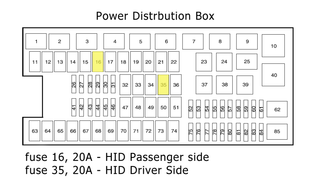
|
Fuse Number
|
Fuse Amperage
|
Fuse Function
|
|
Relay 1
|
|
Powertrain control module power relay for 3.7L, 5.0L, and 6.2L engines
|
|
Relay 2
|
|
Starter
|
|
Relay 3
|
|
Blower motor
|
|
Relay 4
|
|
Rear window defroster
|
|
Relay 5
|
|
High speed electric fan
|
|
Relay 6
|
|
Trailer tow park lamp
|
|
Relay 7
|
|
Run/Start
|
|
Relay 8
|
|
Fuel Pump
|
|
Relay 9
|
|
Trailer tow battery charger
|
|
Relay 10
|
|
3.5L engine PCM
|
|
11
|
30A
|
Power running board motors
|
|
12
|
40A
|
Electric fan
|
|
13
|
30A
|
Starter relay
|
|
14
|
30A
|
Passenger power seats
|
|
15
|
40A
|
Electric fan (6.2L with max trailer tow, SVT raptor has 50A fuse)
|
|
16
|
|
Not in Use
|
|
17
|
30A
|
Trailer brake
|
|
18
|
30A
|
SVT Raptor upfitter 1
|
|
19
|
30A
|
SVT Raptor upfitter 2
|
|
20
|
20A
|
Electronic shift 4X4 module
|
|
21
|
30A
|
Trailer tow battery charge relay power
|
|
22
|
20A
|
Cigarette lighter
|
|
Relay 23
|
|
A/C clutch relay
|
|
Relay 24
|
|
Not in Use
|
|
Relay 25
|
|
3.5L engine vacuum pump
|
|
26
|
10A
|
Powertrain Control Module relay coil, PCM – keeps alive power, and canister vent solenoid (3.7L, 5.0L, and 6.2L engines)
|
|
27
|
20A
|
Fuel pump relay
|
|
28
|
10A
|
Upfitter 4 (SVT Raptor)
|
|
29
|
10A
|
4×4 IWE solenoid
|
|
30
|
10A
|
A/C clutch
|
|
31
|
20A
|
Run/start relay power
|
|
32
|
40A
|
Rear window defroster relay power
|
|
33
|
40A
|
110V AC powerpoint
|
|
34
|
40A
|
PCM relay power (3.7L, 5.0L, and 6.2L engines), (3.5L engine requires 50A fuse)
|
|
35
|
|
Not in Use
|
|
36
|
30A
|
Roll stability control module or RSC/Anti-lock brake system or ABS
|
|
Relay 37
|
|
Trailer tow left-hand stop or turn
|
|
Relay 38
|
|
Trailer tow right-hand stop or turn
|
|
Relay 39
|
|
Backup lamps
|
|
Relay 40
|
|
Electric fan
|
|
41
|
|
Not in Use
|
|
42
|
5A
|
Run/start coil
|
|
43
|
15A
|
TT backup lamp relay power
|
|
44
|
15A
|
SVT Raptor upfitter 3
|
|
45
|
10A
|
Non-6.2L engines alternator sensor
|
|
46
|
10A
|
Brake on/off switch
|
|
47
|
60A
|
Roll stability control and anti=lock brake modules
|
|
48
|
20A
|
Moonroof
|
|
49
|
30A
|
Wipers
|
|
50
|
|
Not in Use
|
|
51
|
40A
|
Blower motor relay
|
|
52
|
5A
|
Run/start -electronic power assisted steering and blower relay coil
|
|
53
|
5A
|
Run/start PCM
|
|
54
|
5A
|
Trailer tow battery charge relay coil, roll stability control or RC/anti-lock brake system or ABS, run/start – 4×4 module, rear window defroster relay coil, and backup lamps
|
|
55
|
|
Not in Use
|
|
56
|
15A
|
Heated mirrors
|
|
57
|
|
Not in Use
|
|
58
|
|
Not in Use
|
|
59
|
|
Not in Use
|
|
Diode 60
|
|
One touch start
|
|
Diode 61
|
|
Not in Use
|
|
Relay 62
|
|
Wiper motor
|
|
63
|
25A
|
Electric fan
|
|
64
|
40A
|
3.5L engine vacuum pump relay power
|
|
65
|
20A
|
Auxiliary power point instrument panel
|
|
66
|
20A
|
Auxiliary powerpoint inside the center console
|
|
67
|
20A
|
TT park lamps relay power
|
|
68
|
25A
|
4x4 module
|
|
69
|
30A
|
Passenger cooled/heated seats
|
|
70
|
|
Not in Use
|
|
71
|
20A
|
Heated rear seats
|
|
72
|
20A
|
Rear auxiliary powerpoint
|
|
73
|
20A
|
TT stop/turn lamps relay power
|
|
74
|
30A
|
Driver Power seat/ memory module
|
|
75
|
15A
|
PCM – voltage power 1 (3.7L, 5.0L, 6.2L engines) PSM module
|
|
76
|
20A
|
PCM – voltage power 2 (general powertrain compartments, mass airflow/intake air temp sensor) (3.7L, 5.0L, and 6.2L engines)
|
|
77
|
10A
|
PCM – voltage power 3 (electric fan relay coil, emission related powertrain components)
|
|
78
|
25A
|
Voltage power 4 – ignition coils (3.5L, 3.7L, 5.0L engines)
|
|
79
|
5A
|
Rain sensor
|
|
80
|
|
Not in Use
|
|
81
|
|
Not in Use
|
|
82
|
|
Not in Use
|
|
83
|
|
Not in Use
|
|
84
|
|
Not in Use
|
|
Relay 85
|
|
Low speed electric fan
|
2012 Ford F150 Fuse Box Diagram and Explanation
The 2012 Ford F150 truck features the same two fuse boxes as found in the 2011 version. The passenger compartment box comes from the 2011 model while the Power Distribution box is based on the one found in the 2009 Ford F150.
Both of these fuse boxes have seen changes since the 2011 version.
Passenger Compartment Fuse Box

|
Fuse Number
|
Fuse Amperage
|
Fuse Function
|
|
1
|
30A
|
Driver side front window
|
|
2
|
15A
|
SYNC
|
|
3
|
30A
|
Passenger side front window
|
|
4
|
10A
|
Interior lamps
|
|
5
|
20A
|
Memory module
|
|
6
|
5A
|
Spare but not in use
|
|
7
|
7.5A
|
Power mirror switch and memory seat module
|
|
8
|
10A
|
Spare but not in use
|
|
9
|
10A
|
GPS module, navigation display and radio display
|
|
10
|
10A
|
Run/accessory relay
|
|
11
|
10A
|
Instrument cluster
|
|
12
|
15A
|
Puddle lamp, backlighting, cargo lamp and interior lighting
|
|
13
|
15A
|
Right turn signals/stop lamps
|
|
14
|
15A
|
Left turn signals/stop lamps
|
|
15
|
15A
|
Reverse lights and high-mounted stop lamps
|
|
16
|
10A
|
Right low beam headlamp
|
|
17
|
10A
|
Left low beam headlamp
|
|
18
|
10A
|
Powertrain control module wakeup, PATS, keypad illumination and brake shift interlock
|
|
19
|
20A
|
Audio amplifier
|
|
20
|
20A
|
Power door locks
|
|
21
|
10A
|
Ambient lighting
|
|
22
|
20A
|
Horn
|
|
23
|
15A
|
Steering wheel control module
|
|
24
|
15A
|
Data Link connector and Steering wheel control module
|
|
25
|
15A
|
Spare but not in use
|
|
26
|
5A
|
Radio frequency module
|
|
27
|
20A
|
Spare not in use
|
|
28
|
15A
|
Ignition switch
|
|
29
|
20A
|
Radio or navigation
|
|
30
|
15A
|
Front parking lamps
|
|
31
|
5A
|
Brake on/off engine & IP
|
|
32
|
15A
|
Moonroof, automatic dimming/compass, power windows and locks
|
|
33
|
10A
|
Heated seats
|
|
34
|
10A
|
SVT Raptor off-road indicator, 4×4 switch, reverse sensing system, and rear video
|
|
35
|
5A
|
SVT Raptor hill descent switch
|
|
36
|
10A
|
Occupant classification system module and restraint control module
|
|
37
|
10A
|
Trailer brake control
|
|
38
|
10A
|
AM/FM radio, delayed accessory – 110V powerpoint
|
|
39
|
15A
|
High beam headlamps
|
|
40
|
10A
|
Rear park lamps
|
|
41
|
7.5A
|
SVT Raptor upfitter switch and passenger airbag deactivation indicator
|
|
42
|
5A
|
Overdrive cancel switch
|
|
43
|
10A
|
Spare not in use
|
|
44
|
10A
|
Spare not in use
|
|
45
|
5A
|
Spare not in use
|
|
46
|
10A
|
Climate control module
|
|
47
|
15A
|
Exterior mirror turn signals and fog lamps
|
|
ATO Circuit Breaker 48
|
30A
|
Power sliding back window and power rear windows
|
|
Relay 49
|
|
Delayed accessory
|
Power Distribution Box
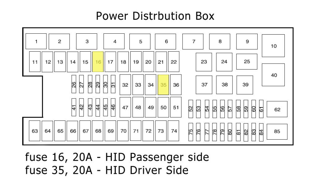
|
Fuse Number
|
Fuse Amperage
|
Fuse Function
|
|
Relay 1
|
|
Powertrain control module power relay for 3.7L, 5.0L, and 6.2L engines
|
|
Relay 2
|
|
Starter
|
|
Relay 3
|
|
Blower motor
|
|
Relay 4
|
|
Rear window defroster
|
|
Relay 5
|
|
Hi-speed electric fan
|
|
Relay 6
|
|
Trailer tow park lamp
|
|
Relay 7
|
|
Run/start
|
|
Relay 8
|
|
Fuel Pump
|
|
Relay 9
|
|
Trailer tow battery charger
|
|
Relay 10
|
|
3.5L engine PCM
|
|
11
|
30A
|
Power running board motors
|
|
12
|
40A
|
Electric fan 6.2L with max trailer tow, SVT raptor version requires 50A fuse)
|
|
13
|
30A
|
Starter relay
|
|
14
|
30A
|
Passenger power seats
|
|
15
|
40A
|
Electric fan (6.2L with max trailer tow, SVT raptor version requires 50A fuse.)
|
|
16
|
|
Not in Use
|
|
17
|
30A
|
Trailer brake
|
|
18
|
30A
|
SVT Raptor upfitter 1
|
|
19
|
30A
|
SVT Raptor upfitter 2
|
|
20
|
20A
|
Electronic shift 4X4 module
|
|
21
|
30A
|
Trailer tow the battery charge relay power
|
|
22
|
20A
|
Cigarette lighter
|
|
Relay 23
|
|
A/C clutch relay
|
|
Relay 24
|
|
Not in Use
|
|
Relay 25
|
|
3.5L engine vacuum pump
|
|
26
|
10A
|
Powertrain control module relay coil, PCM – keep alive power, and canister vent solenoid (3.7L, 5.0L, and 6.2L engines)
|
|
27
|
20A
|
Fuel pump relay power
|
|
28
|
10A
|
Upfitter 4 (SVT Raptor)
|
|
29
|
10A
|
4x4 IWE solenoid
|
|
30
|
10A
|
A/C clutch
|
|
31
|
15A
|
Run/start relay power
|
|
32
|
40A
|
Rear window defroster relay power, heated mirror relay power
|
|
33
|
40A
|
110V AC powerpoint
|
|
34
|
40A
|
Powertrain control module relay power (3.7L, 5.0L, and 6.2L engines)
|
|
35
|
|
Not in Use
|
|
36
|
30A
|
Roll stability control module (RSC) and Anti-lock brake system (ABS)
|
|
Relay 37
|
|
Trailer tow left-hand stop or turn
|
|
Relay 38
|
|
Trailer tow right-hand stop or turn
|
|
Relay 39
|
|
TT backup lamps
|
|
Relay 40
|
|
Electric fan relay
|
|
41
|
15A
|
SVT raptor front camera washer
|
|
42
|
5A
|
Run/start coil
|
|
43
|
15A
|
TT backup lamp relay power
|
|
44
|
15A
|
SVT Raptor upfitter 3
|
|
45
|
10A
|
Non-6.2L engines alternator sensor
|
|
46
|
10A
|
Brake on/off switch
|
|
47
|
60A
|
Roll stability control module and anti-lock brakes
|
|
48
|
20A
|
Moonroof
|
|
49
|
30A
|
Wipers
|
|
50
|
|
Not in Use
|
|
51
|
40A
|
Blower motor relay
|
|
52
|
5A
|
Run/start -electronic power assisted steering and blower relay coil
|
|
53
|
5A
|
PCM run/start
|
|
54
|
5A
|
Trailer tow battery charge relay coil, RSC/ABS, run/start – 4×4 module, rear window defroster relay coil, SVT raptor front camera relay coil, and backup lamps
|
|
55
|
|
Not in Use
|
|
56
|
15A
|
Heated mirrors
|
|
57
|
|
Not in Use
|
|
58
|
|
Not in Use
|
|
59
|
|
Not in Use
|
|
Diode 60
|
|
Not in Use
|
|
Diode 61
|
|
Not in Use
|
|
Relay 62
|
|
Wiper motor
|
|
63
|
25A
|
Electric fan
|
|
64
|
40A
|
3.5L engine vacuum pump relay power
|
|
65
|
20A
|
Auxiliary power point instrument panel
|
|
66
|
20A
|
Auxiliary powerpoint inside the center console
|
|
67
|
20A
|
TT park lamps relay power
|
|
68
|
25A
|
4x4 module
|
|
69
|
30A
|
Passenger cooled/heated seats
|
|
70
|
|
Not in Use
|
|
71
|
20A
|
Heated rear seats
|
|
72
|
20A
|
Rear auxiliary powerpoint
|
|
73
|
20A
|
TT stop/turn lamps relay power
|
|
74
|
30A
|
Driver power seat/memory module
|
|
75
|
15A
|
Powertrain control module VPWR1 (3.5L, 3.7L, 5.0L, 6.2L engines) PSM module
|
|
76
|
20A
|
Powertrain control module VPWR2 (general powertrain compartments, mass airflow/intake air temp sensor) (3.7L, 5.0L, and 6.2L engines) Alternately (3.5L general powertrain compartments, canister vent solenoid)
|
|
77
|
10A
|
PCM – VPWR3 (electric fan relay coil, emission related powertrain components
|
|
78
|
15A
|
Ignition coils and VPWR4 (3.5L, 3.7L, 5.0L engines) (20A fuse for 6.2L engines)
|
|
79
|
5A
|
Rain sensor
|
|
80
|
|
Not in Use
|
|
81
|
|
Not in Use
|
|
82
|
|
Not in Use
|
|
83
|
|
Not in Use
|
|
84
|
|
A/C clutch
|
|
Relay 85
|
|
Low-speed electric fan
|
2013 Ford F150 Fuse Diagram and Explanation
The 2013 Ford F150 truck features the same two fuse boxes as found in the 2011 version. The passenger compartment box comes from the 2011 model while the Power Distribution box is based on the one found in the 2009 Ford F150.
Both of these fuse boxes have seen changes since the 2011 version.
Passenger Compartment Fuse Box

|
Fuse Number
|
Fuse Amperage
|
Fuse Function
|
|
1
|
30A
|
Driver side front window
|
|
2
|
15A
|
SYNC and an eight-inch display module
|
|
3
|
30A
|
Passenger side front window
|
|
4
|
10A
|
Interior lamps
|
|
5
|
20A
|
Memory module
|
|
6
|
5A
|
Spare but not in use
|
|
7
|
7.5A
|
Power mirror switch and memory seat module
|
|
8
|
10A
|
Spare but not in use
|
|
9
|
10A
|
Electric finish panel module GPS module and radio display
|
|
10
|
10A
|
Run/accessory relay
|
|
11
|
10A
|
Instrument cluster
|
|
12
|
15A
|
Puddle lamp, backlighting, cargo lamp and interior lighting
|
|
13
|
15A
|
Right turn signals/stop lamps
|
|
14
|
15A
|
Left turn signals/stop lamps
|
|
15
|
15A
|
Reverse lights and high-mounted stop lamps
|
|
16
|
10A
|
Right low beam headlamp
|
|
17
|
10A
|
Left low beam headlamp
|
|
18
|
10A
|
Powertrain control module wakeup, PATS, keypad illumination and brake shift interlock
|
|
19
|
20A
|
Audio amplifier
|
|
20
|
20A
|
Power door locks
|
|
21
|
10A
|
Spare not in use
|
|
22
|
20A
|
Horn
|
|
23
|
15A
|
Steering wheel control module
|
|
24
|
15A
|
Data Link connector and Steering wheel control module
|
|
25
|
15A
|
Spare but not in use
|
|
26
|
5A
|
Radio frequency module
|
|
27
|
20A
|
Spare not in use
|
|
28
|
15A
|
Ignition switch
|
|
29
|
20A
|
Radio
|
|
30
|
15A
|
Front parking lamps
|
|
31
|
5A
|
Brake on/off engine & instrument panel
|
|
32
|
15A
|
Moonroof, automatic dimming/compass, trailer tow power telescopic mirrors power windows and locks
|
|
33
|
10A
|
Heated seats
|
|
34
|
10A
|
SVT Raptor off-road indicator, 4×4 switch, reverse sensing system, front & rear video and camera splice module
|
|
35
|
5A
|
SVT Raptor hill descent switch
|
|
36
|
10A
|
Occupant classification system module and restraint control module
|
|
37
|
10A
|
Trailer brake control
|
|
38
|
10A
|
AM/FM radio, delayed accessory – 110V powerpoint
|
|
39
|
15A
|
High beam headlamps
|
|
40
|
10A
|
Rear park lamps
|
|
41
|
7.5A
|
SVT Raptor upfitter switch and passenger airbag deactivation indicator
|
|
42
|
5A
|
Overdrive cancel switch
|
|
43
|
10A
|
Spare not in use
|
|
44
|
10A
|
Spare not in use
|
|
45
|
5A
|
Spare not in use
|
|
46
|
10A
|
Climate control module
|
|
47
|
15A
|
Exterior mirror turn signals and fog lamps
|
|
ATO Circuit Breaker 48
|
30A
|
Power sliding back window and power rear windows
|
|
Relay 49
|
|
Delayed accessory
|
Power Distribution Fuse Box
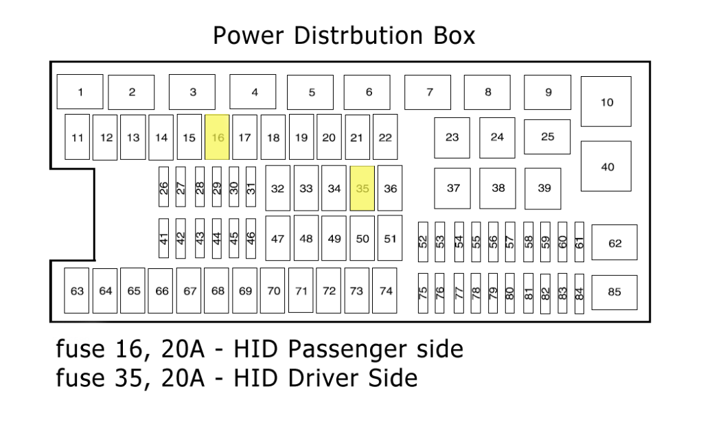
|
Fuse Number
|
Fuse Amperage
|
Fuse Function
|
|
Relay 1
|
|
Powertrain control module power relay for 3.7L, 5.0L, and 6.2L engines
|
|
Relay 2
|
|
Starter
|
|
Relay 3
|
|
Blower motor
|
|
Relay 4
|
|
Rear window defroster
|
|
Relay 5
|
|
High-speed electric fan
|
|
Relay 6
|
|
Trailer tow park lamp
|
|
Relay 7
|
|
Run/start
|
|
Relay 8
|
|
Fuel Pump
|
|
Relay 9
|
|
Trailer tow battery charger
|
|
Relay 10
|
|
3.5L engine Powertrain control module
|
|
11
|
30A
|
Power running board motors
|
|
12
|
40A/50A
|
Electric fan. (3.7L and 5.0L engines)/ electric fan (3.5L and 6.2L with max trailer tow, SVT raptor)
|
|
13
|
30A
|
Starter relay
|
|
14
|
30A
|
Passenger power seats
|
|
15
|
40A/50A
|
Electric fan (3.7L and 5.0L engines)/ electric fan (3.5L and 6.2L with max trailer tow, SVT raptor)
|
|
16
|
20A
|
High-intensity discharge headlamp -passenger side
|
|
17
|
30A
|
Trailer brake
|
|
18
|
30A
|
SVT Raptor upfitter 1
|
|
19
|
30A
|
SVT Raptor upfitter 2
|
|
20
|
20A
|
Electric shift and 4x4 module
|
|
21
|
30A
|
Trailer tow battery charge relay power
|
|
22
|
20A
|
Instrument panel auxiliary powerpoint
|
|
Relay 23
|
|
A/C clutch relay
|
|
Relay 24
|
|
Not in Use
|
|
Relay 25
|
|
Not in Use
|
|
26
|
10A
|
Powertrain control module relay, keep alive power PCM and canister vent solenoid (3.7L, 5.0L, and 6.2L engines)
|
|
27
|
20A
|
Fuel pump relay
|
|
28
|
10A
|
Upfitter 4 (SVT Raptor)
|
|
29
|
10A
|
4x4 IWE solenoid
|
|
30
|
10A
|
A/C clutch
|
|
31
|
15A
|
Run/start relay power
|
|
32
|
40A
|
Rear window defroster relay power and heated mirror relay power
|
|
33
|
40A
|
110V AC powerpoint
|
|
34
|
40A
|
PCM relay power for 3.5L engines
|
|
35
|
20A
|
Driver-side high-intensity discharge headlamps
|
|
36
|
30A
|
RSC/ABS
|
|
Relay 37
|
|
Trailer tow left-hand stop or turn
|
|
Relay 38
|
|
Trailer tow right-hand stop or turn
|
|
Relay 39
|
|
Backup lamps
|
|
Relay 40
|
|
Electric fan
|
|
41
|
15A
|
SVT Raptor front camera washer
|
|
42
|
5A
|
Run/start coil
|
|
43
|
15A
|
TT backup lamp relay
|
|
44
|
15A
|
SVT Raptor upfitter 3, trailer tow power-folding mirrors
|
|
45
|
10A
|
Alternator sensor (3.5L, 3.7L, and 5.0L engines)
|
|
46
|
10A
|
Brake on/off switch
|
|
47
|
60A
|
RSC/ABS module
|
|
48
|
20A
|
Moonroof
|
|
49
|
30A
|
Wipers relay power
|
|
50
|
|
Not in Use
|
|
51
|
40A
|
Blower motor relay
|
|
52
|
5A
|
Run/start electronic power assisted steering and blower relay coil
|
|
53
|
5A
|
PCM run/start
|
|
54
|
5A
|
trailer tow battery charge relay coil, RSC/ABS, run/start – 4×4 module, rear window defroster relay coil, SVT Raptor front camera washer relay coil and back up lamps
|
|
55
|
|
Not in Use
|
|
56
|
15A
|
Heated windows
|
|
57
|
|
Not in Use
|
|
58
|
|
Not in Use
|
|
59
|
|
Not in Use
|
|
Diode 60
|
|
Not in Use
|
|
Diode 61
|
|
Not in Use
|
|
Relay 62
|
|
Not in Use
|
|
63
|
25A
|
Electric fan relay power
|
|
64
|
|
Not in Use
|
|
65
|
20A
|
Auxiliary power point instrument panel
|
|
66
|
20A
|
Auxiliary powerpoint inside the center console
|
|
67
|
20A
|
TT park lamps relay power
|
|
68
|
25A
|
4x4 module and 4x2 locker module
|
|
69
|
30A
|
Front cooled/heated seats
|
|
70
|
|
Not in Use
|
|
71
|
20A
|
Heated rear seats
|
|
72
|
20A
|
Rear auxiliary powerpoint
|
|
73
|
20A
|
TT stop/turn lamps relay power
|
|
74
|
30A
|
Driver Power seat/memory module
|
|
75
|
15A/25A
|
PCM – VPWR11 (3.7L, 5.0L, 6.2L engines) PSM module (3.5L engines require 25A fuse)
|
|
76
|
20A
|
PCM – VPWR2 (general powertrain compartments, mass airflow/intake air temp sensor) (3.7L, 5.0L, and 6.2L engines) (general powertrain compartments, canister vent solenoid for 3.5L engine)
|
|
77
|
10A
|
PCM – VPWR3 (electric fan relay coil, emission related powertrain components)
|
|
78
|
15A/20A
|
VPWR4 – ignition coils (3.5L, 3.7L, 5.0L engines)/ PCM – VPWR4 – ignition coils (6.2L engine)
|
|
79
|
5A
|
Rain sensor
|
|
80
|
|
Not in Use
|
|
81
|
|
Not in Use
|
|
82
|
|
Not in Use
|
|
83
|
|
Not in Use
|
|
84
|
|
Not in Use
|
|
Relay 85
|
|
Low-Speed electric fan
|
2014 Ford F150 Fuse Box Diagram and Explanation
The 2014 Ford F150 features the Passenger Compartment Fuse Box from the 2011 model and the power distribution box from the 2009 model. Both have seen considerable changes over the years and are located in the same general area that they have been since 1999.
Passenger Compartment Fuse Box

|
Fuse Number
|
Fuse Amperage
|
Fuse Function
|
|
1
|
30A
|
Driver side front window
|
|
2
|
15A
|
SYNC and an eight-inch display module
|
|
3
|
30A
|
Passenger side front window
|
|
4
|
10A
|
Interior lamps
|
|
5
|
20A
|
Memory module
|
|
6
|
5A
|
Spare but not in use
|
|
7
|
7.5A
|
Power mirror switch and memory seat module
|
|
8
|
10A
|
Spare but not in use
|
|
9
|
10A
|
Electric finish panel module GPS module and radio display
|
|
10
|
10A
|
Run/accessory relay
|
|
11
|
10A
|
Instrument cluster
|
|
12
|
15A
|
Puddle lamp, backlighting, cargo lamp and interior lighting
|
|
13
|
15A
|
Right turn signals/stop lamps
|
|
14
|
15A
|
Left turn signals/stop lamps
|
|
15
|
15A
|
Reverse lights and high-mounted stop lamps
|
|
16
|
10A
|
Right low beam headlamp
|
|
17
|
10A
|
Left low beam headlamp
|
|
18
|
10A
|
Powertrain control module wakeup, PATS, keypad illumination and brake shift interlock
|
|
19
|
20A
|
Audio amplifier
|
|
20
|
20A
|
Power door locks
|
|
21
|
10A
|
Spare not in use
|
|
22
|
20A
|
Horn
|
|
23
|
15A
|
Steering wheel control module
|
|
24
|
15A
|
Data Link connector and Steering wheel control module
|
|
25
|
15A
|
Spare but not in use
|
|
26
|
5A
|
Radio frequency module
|
|
27
|
20A
|
Spare not in use
|
|
28
|
15A
|
Ignition switch
|
|
29
|
20A
|
Radio
|
|
30
|
15A
|
Front parking lamps
|
|
31
|
5A
|
Brake on/off, instrument panel and engine
|
|
32
|
15A
|
Moonroof, automatic dimming/compass, trailer tow power telescopic mirrors power windows and locks
|
|
33
|
10A
|
Rear heated seats
|
|
34
|
10A
|
SVT Raptor off-road indicator, 4×4 switch, reverse sensing system, front & rear video and camera splice module
|
|
35
|
5A
|
SVT Raptor hill descent switch
|
|
36
|
10A
|
Occupant classification system module and restraint control module
|
|
37
|
10A
|
Trailer brake control
|
|
38
|
10A
|
AM/FM radio, delayed accessory – 110V powerpoint
|
|
39
|
15A
|
High beam headlamps
|
|
40
|
10A
|
Rear park lamps
|
|
41
|
7.5A
|
SVT Raptor auxiliary switch and passenger airbag deactivation indicator
|
|
42
|
5A
|
Overdrive cancel switch
|
|
43
|
10A
|
Spare not in use
|
|
44
|
10A
|
Spare not in use
|
|
45
|
5A
|
Spare not in use
|
|
46
|
10A
|
Climate control module
|
|
47
|
15A
|
Exterior mirror turn signals and fog lamps
|
|
ATO Circuit Breaker 48
|
30A
|
Power sliding back window and power rear windows
|
|
Relay 49
|
|
Delayed accessory
|
Power Distribution Box
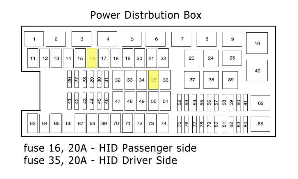
|
Fuse Number
|
Fuse Amperage
|
Fuse Function
|
|
Relay 1
|
|
Powertrain control module power relay for 3.7L, 5.0L, and 6.2L engines
|
|
Relay 2
|
|
Starter
|
|
Relay 3
|
|
Blower motor
|
|
Relay 4
|
|
Rear window defroster
|
|
Relay 5
|
|
High-speed electric fan
|
|
Relay 6
|
|
Trailer tow park lamp
|
|
Relay 7
|
|
Run/start
|
|
Relay 8
|
|
Fuel Pump
|
|
Relay 9
|
|
Trailer tow battery charger
|
|
Relay 10
|
|
3.5L engine Powertrain control module
|
|
11
|
30A
|
Power running board motors
|
|
12
|
40A/50A
|
Electric fan. (3.7L and 5.0L engines)/ electric fan (3.5L and 6.2L with max trailer tow, SVT raptor)
|
|
13
|
30A
|
Starter relay
|
|
14
|
30A
|
Passenger power seats
|
|
15
|
40A/50A
|
Electric fan (3.7L and 5.0L engines)/ electric fan (3.5L and 6.2L with max trailer tow, SVT raptor)
|
|
16
|
20A
|
High-intensity discharge headlamp -passenger side
|
|
17
|
30A
|
Trailer brake
|
|
18
|
30A
|
SVT Raptor auxiliary switch 1
|
|
19
|
30A
|
SVT Raptor auxiliary switch 2
|
|
20
|
20A
|
Electric shift and 4x4 module
|
|
21
|
30A
|
Trailer tow battery charge relay power
|
|
22
|
20A
|
Instrument panel auxiliary powerpoint
|
|
Relay 23
|
|
A/C clutch relay
|
|
Relay 24
|
|
Not in Use
|
|
Relay 25
|
|
Not in Use
|
|
26
|
10A
|
Powertrain control module relay, keep alive power PCM and canister vent solenoid (3.7L, 5.0L, and 6.2L engines)
|
|
27
|
20A
|
Fuel pump relay
|
|
28
|
10A
|
Auxiliary switch 4 (SVT Raptor)
|
|
29
|
10A
|
4x4 IWE solenoid
|
|
30
|
10A
|
A/C clutch relay power
|
|
31
|
15A
|
Run/start relay power
|
|
32
|
40A
|
Rear window defroster relay power and heated mirror relay power
|
|
33
|
40A
|
110V AC powerpoint
|
|
34
|
40A/50A
|
PCM relay power (3.7L, 5.0L, and 6.2L engines)/PCM relay power for 3.5L engines
|
|
35
|
20A
|
Driver-side high-intensity discharge headlamps
|
|
36
|
30A
|
RSC/ABS
|
|
Relay 37
|
|
Trailer tow left-hand stop or turn
|
|
Relay 38
|
|
Trailer tow right-hand stop or turn
|
|
Relay 39
|
|
Backup lamps
|
|
Relay 40
|
|
Electric fan
|
|
41
|
15A
|
SVT Raptor front camera washer
|
|
42
|
5A
|
Run/start coil
|
|
43
|
15A
|
TT backup lamp relay power
|
|
44
|
15A
|
SVT Raptor alternator sensor 3, trailer tow power-folding mirrors
|
|
45
|
10A
|
Alternator sensor (3.5L, 3.7L, and 5.0L engines)
|
|
46
|
10A
|
Brake on/off switch
|
|
47
|
60A
|
RSC/ABS module
|
|
48
|
20A
|
Moonroof
|
|
49
|
30A
|
Wipers relay power
|
|
50
|
|
Not in Use
|
|
51
|
40A
|
Blower motor relay
|
|
52
|
5A
|
Run/start electronic power assisted steering and blower relay coil
|
|
53
|
5A
|
PCM run/start
|
|
54
|
5A
|
Trailer tow battery charge relay coil, RSC/ABS, run/start – 4×4 module, rear window defroster relay coil, SVT Raptor front camera washer relay coil and back up lamps
|
|
55
|
|
Not in Use
|
|
56
|
15A
|
Heated mirrors
|
|
57
|
|
Not in Use
|
|
58
|
|
Not in Use
|
|
59
|
|
Not in Use
|
|
Diode 60
|
|
Not in Use
|
|
Diode 61
|
|
Not in Use
|
|
Relay 62
|
|
Wiper motor
|
|
63
|
25A
|
Electric fan relay power
|
|
64
|
|
Not in Use
|
|
65
|
20A
|
Auxiliary power point instrument panel
|
|
66
|
20A
|
Auxiliary powerpoint inside the center console
|
|
67
|
20A
|
TT park lamps relay power
|
|
68
|
25A
|
4x4 module and 4x2 locker module
|
|
69
|
30A
|
Front cooled/heated seats
|
|
70
|
|
Not in Use
|
|
71
|
20A
|
Heated rear seats
|
|
72
|
20A
|
Rear auxiliary powerpoint
|
|
73
|
20A
|
TT stop/turn lamps relay power
|
|
74
|
30A
|
Driver Power seat/memory module
|
|
75
|
15A/25A
|
PCM – VPWR11 (3.7L, 5.0L, 6.2L engines) PSM module (3.5L engines require 25A fuse)
|
|
76
|
20A
|
PCM – VPWR2 (general powertrain compartments, mass airflow/intake air temp sensor) (3.7L, 5.0L, and 6.2L engines) (general powertrain compartments, canister vent solenoid for 3.5L engine)
|
|
77
|
10A
|
PCM – VPWR3 (electric fan relay coil, emission related powertrain components)
|
|
78
|
15A/20A
|
VPWR4 – ignition coils (3.5L, 3.7L, 5.0L engines)/ PCM – VPWR4 – ignition coils (6.2L engine)
|
|
79
|
5A
|
Rain sensor
|
|
80
|
|
Not in Use
|
|
81
|
|
Not in Use
|
|
82
|
|
Not in Use
|
|
83
|
|
Not in Use
|
|
84
|
|
Not in Use
|
|
Relay 85
|
|
Low-Speed electric fan
|
2015 Ford F150 Fuse Box Diagram and Explanation
The 2015 Ford F150 underwent a big overhaul in terms of fuse boxes as both the power distribution box and the Passenger Compartment Fuse Boxes were completely changed. They of course still remained in the same general locations within the truck.
Passenger Compartment Fuse Box

|
Fuse Number
|
Fuse Amperage
|
Fuse Function
|
|
1
|
10A
|
Glove box, power seat relay, demand lamp relay, overhead console, vanity lamps, dome, map lamps and courtesy lamps
|
|
2
|
5A
|
Memory seat switches, lumbar motor and memory module logic
|
|
3
|
20A
|
Driver door lock motor
|
|
4
|
5A
|
Trailer brake control
|
|
5
|
20A
|
Not in Use
|
|
6
|
10A
|
Not in Use
|
|
7
|
10A
|
Not in use
|
|
8
|
10A
|
Not in Use
|
|
9
|
10A
|
Not in Use
|
|
10
|
5A
|
Spare not in use
|
|
11
|
5A
|
Combined sensor module
|
|
12
|
5A
|
Climate head module and data link converter
|
|
13
|
5A
|
Cluster and SCCM
|
|
14
|
10A
|
Brake
|
|
15
|
10A
|
Smart data link converter
|
|
16
|
15A
|
Tailgate release
|
|
17
|
5A
|
Passive entry, passive start-stop switch, HUD and ignition switch
|
|
18
|
5A
|
Key inhibit solenoid
|
|
19
|
7.5A
|
Tow haul (O/D) cancel for floor or column shifter
|
|
20
|
5A
|
Not in Use
|
|
21
|
5A
|
Heads up display (HUD), in case temp with humidity sensor
|
|
22
|
5A
|
Power Seats and EPB
|
|
23
|
10A
|
Driver side window, PDGR switch and moonroof
|
|
24
|
20A
|
Central lock/unlock
|
|
25
|
30A
|
Driver door control module
|
|
26
|
30A
|
Passenger door control module
|
|
27
|
30A
|
Moonroof and Vista roof
|
|
28
|
20A
|
Not in Use
|
|
29
|
30A
|
Not in Use
|
|
30
|
30A
|
Not in Use
|
|
31
|
15A
|
Adjustable pedal switch and motor
|
|
32
|
10A
|
Radio frequency receiver, SYNC1 STNC2, GPS and multifunction display
|
|
33
|
20A
|
Radio
|
|
34
|
30A
|
Run/start relay
|
|
35
|
5A
|
Restraints module
|
|
36
|
15A
|
Heated steering wheel module, 360 camera module, rear heated seats and rear view mirror
|
|
37
|
15A
|
Power distribution box run/start relay
|
|
Circuit Breaker 38
|
|
Rear window switches and motors
|
Power Distribution Fuse Box
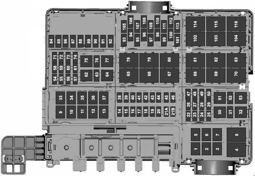
|
Fuse Number
|
Fuse Amperage
|
Fuse Function
|
|
1
|
|
Not in Use
|
|
2
|
|
Not in Use
|
|
3
|
|
Not in Use
|
|
Relay 4
|
|
Telescoping side-view mirror
|
|
5
|
40A
|
Rear window defroster
|
|
6
|
|
Not in Use
|
|
7
|
|
Not in Use
|
|
Relay 8
|
|
Telescoping side-view mirror
|
|
9
|
|
Not in Use
|
|
10
|
|
Not in Use
|
|
11
|
60A
|
Automatic brake system motor
|
|
12
|
50A
|
Body control module 1
|
|
13
|
60
|
Body control module 2
|
|
14
|
20A
|
Amplifier
|
|
15
|
25A
|
4x4
|
|
16
|
10A
|
Spotlight module
|
|
17
|
15A
|
Heated seat
|
|
18
|
10A
|
Steering column lock
|
|
19
|
10A
|
Power seats
|
|
20
|
15A
|
Rear heated seats and snowplow
|
|
21
|
|
Not in Use
|
|
22B
|
|
Not in Use
|
|
22
|
30A
|
Windshield wiper motor
|
|
23
|
15A
|
Rain sensor
|
|
24
|
25A
|
Series fan feed
|
|
25
|
|
Not in Use
|
|
26
|
30A
|
Driver seat motors
|
|
27
|
30A
|
Passenger power seat
|
|
28
|
30A
|
Climate controlled seat
|
|
29
|
|
Not in Use
|
|
Relay 30
|
|
Air conditioner clutch
|
|
31
|
|
Not in Use
|
|
Relay 32
|
|
Not in Use
|
|
33
|
50A
|
Electric fan 3
|
|
34
|
25A
|
Trailer tow park lamps
|
|
35
|
20A
|
Trailer tow stop/turn relay
|
|
36
|
25A
|
Trailer tow lamps module
|
|
37
|
50A
|
Electric fan 1
|
|
38
|
10A
|
Alt-A sensor
|
|
39
|
10A
|
Integrated wheel end solenoid
|
|
40
|
15A
|
E-locker
|
|
41
|
10A
|
Telescoping mirror
|
|
42
|
30A
|
Transmission fluid pump
|
|
43
|
25A
|
Horn
|
|
44
|
10A
|
Air conditioner clutch
|
|
45
|
10A
|
Powertrain control module relay coil
|
|
46
|
10A
|
Wiper relay coil
|
|
47
|
|
Not in Use
|
|
48
|
|
Not in Use
|
|
49
|
30A
|
Trailer brake control module
|
|
50
|
30A
|
Power running boards
|
|
Relay 51
|
|
Fuel Pump
|
|
52
|
|
Not in Use
|
|
53
|
|
Not in Use
|
|
54
|
30A
|
Voltage quality module and body control module voltage quality module feed
|
|
55
|
40A
|
Body control module RP2 feed
|
|
56
|
20A
|
Fuel pump
|
|
57
|
30A
|
Right hand EPB actuator
|
|
58
|
30A
|
Left hand EPB actuator
|
|
59
|
30A
|
Starter
|
|
60
|
40A
|
Blower motor
|
|
61
|
30A
|
Brake control module and automatic brake system valves
|
|
Relay 62
|
|
Power seat
|
|
63
|
15A
|
Heated mirrors
|
|
Relay 64
|
|
Not in Use
|
|
Relay 65
|
|
Starter
|
|
Relay 66
|
|
Powertrain control module
|
|
Relay 67
|
|
Windscreen wiper
|
|
Relay 68
|
|
Blower motor
|
|
Relay 69
|
|
Power sliding back window
|
|
Relay 70
|
|
Electric fan 1
|
|
71
|
|
Not in Use
|
|
72
|
25A
|
4x4
|
|
73
|
|
Not in Use
|
|
74
|
30A
|
PDGR motor
|
|
Relay 75
|
|
Horn
|
|
76
|
|
Not in Use
|
|
Relay 77
|
|
Steering column lock
|
|
Relay 78
|
|
Not in Use
|
|
Relay 79
|
|
Trailer tow parking lamp
|
|
Relay 80
|
|
Rear window defroster
|
|
Relay 81
|
|
Not in Use
|
|
Relay 82
|
|
PDGR close
|
|
Relay 83
|
|
Not in Use
|
|
84
|
|
Not in Use
|
|
85
|
|
Not in Use
|
|
86
|
|
Not in Use
|
|
87
|
10A
|
Trailer tow backup lamps
|
|
88
|
|
Not in Use
|
|
89
|
20A
|
Cigarette lighter/powerpoint 1
|
|
90
|
20
|
Powerpoint 2
|
|
91
|
20A
|
Powerpoint 3
|
|
92
|
20A
|
Powerpoint 4
|
|
93
|
10A/25A
|
PFI vehicle power 1/GTDI vehicle power 1
|
|
94
|
|
Not in Use
|
|
95
|
25A
|
Vehicle power 2
|
|
96
|
|
Not in Use
|
|
97
|
10A
|
Vehicle power 3
|
|
98
|
|
Not in Use
|
|
99
|
15A/20A
|
GTDI vehicle power 4/PFI vehicle power 4
|
|
100
|
|
Not in Use
|
|
101
|
|
Not in Use
|
|
Relay 102
|
|
Snow plow
|
|
Relay 103
|
|
Not in Use
|
|
Relay 104
|
|
Fan 3
|
|
105
|
10A
|
Power steering
|
|
106
|
|
Not in Use
|
|
107
|
10A
|
Anti-lock brakes (ABS)
|
|
108
|
|
Not in Use
|
|
109
|
10A
|
Powertrain control module
|
|
110
|
10A
|
Adaptive cruise control and 4x4 run/start
|
|
111
|
10A
|
Transmission pump run/start
|
|
112
|
|
Not in Use
|
|
113
|
5A
|
Rearview camera, left-hand blind spot information system, voltage quality module and front view camera
|
|
Relay 114
|
|
Fan 2
|
|
Relay 115
|
|
Not in Use
|
|
Relay 116
|
|
Not in Use
|
2016 Ford F150 Fuse Box Diagram and Explanation
The 2016 Ford F150 fuse boxes are the same as in 2015 with just a few changes. The passenger compartment box is the one which has seen some changes but the power distribution box is pretty much identical to the 2015 version.
Passenger Compartment Fuse Box

|
Fuse Number
|
Fuse Amperage
|
Fuse Function
|
|
1
|
10A
|
Glove box, power seat relay, demand lamp relay, overhead console, vanity lamps, dome, map lamps and courtesy lamps
|
|
2
|
5A
|
Memory seat switches, lumbar motor and memory module logic
|
|
3
|
20A
|
Driver door lock motor
|
|
4
|
5A
|
Trailer brake control
|
|
5
|
20A
|
Not in Use
|
|
6
|
10A
|
Not in Use
|
|
7
|
10A
|
Not in use
|
|
8
|
10A
|
Not in Use
|
|
9
|
10A
|
Not in Use
|
|
10
|
5A
|
Spare not in use
|
|
11
|
5A
|
Combined sensor module
|
|
12
|
5A
|
Climate head module and data link converter
|
|
13
|
5A
|
Cluster and SCCM
|
|
14
|
10A
|
Brake
|
|
15
|
10A
|
Smart data link converter
|
|
16
|
15A
|
Tailgate release
|
|
17
|
5A
|
Passive entry, passive start-stop switch, HUD and ignition switch
|
|
18
|
5A
|
Key inhibit solenoid
|
|
19
|
7.5A
|
Tow haul (O/D) cancel for floor or column shifter
|
|
20
|
5A
|
Not in Use
|
|
21
|
5A
|
Heads up display (HUD), in case temp with humidity sensor
|
|
22
|
5A
|
Power Seats and EPB
|
|
23
|
10A
|
Driver side window, PDGR switch, driver side window, inverter, Vista roof and moonroof
|
|
24
|
20A
|
Central lock/unlock
|
|
25
|
30A
|
Driver door control module
|
|
26
|
30A
|
Passenger door control module
|
|
27
|
30A
|
Moonroof and Vista roof
|
|
28
|
20A
|
Not in Use
|
|
29
|
30A
|
Not in Use
|
|
30
|
30A
|
Not in Use
|
|
31
|
15A
|
Adjustable pedal switch and motor
|
|
32
|
10A
|
Radio frequency receiver, SYNC1 STNC2, GPS and multifunction display
|
|
33
|
20A
|
Radio
|
|
34
|
30A
|
Run/start relay
|
|
35
|
5A
|
Restraints module
|
|
36
|
15A
|
Heated steering wheel module, 360 camera module, rear heated seats and rear view mirror
|
|
37
|
20A
|
Power distribution box run/start relay
|
|
Circuit Breaker 38
|
|
Rear window switches and motors
|
Power Distribution Fuse Box
The 2016 Ford F150 Power Distribution Fuse Box did not change from the 2015 layout. Scroll back to the 2015 table to see this layout.
2017 Ford Fusion Fuse Box Diagram and Explanation
The Ford F150 truck used both of the same fuse boxes from the 2015 model year but did have several big changes when it came to fuse functions. The passenger compartment box can be found near the brake pedal under the steering wheel while the power distribution box is in the left hand side of the engine bay.
Passenger Compartment Fuse Box
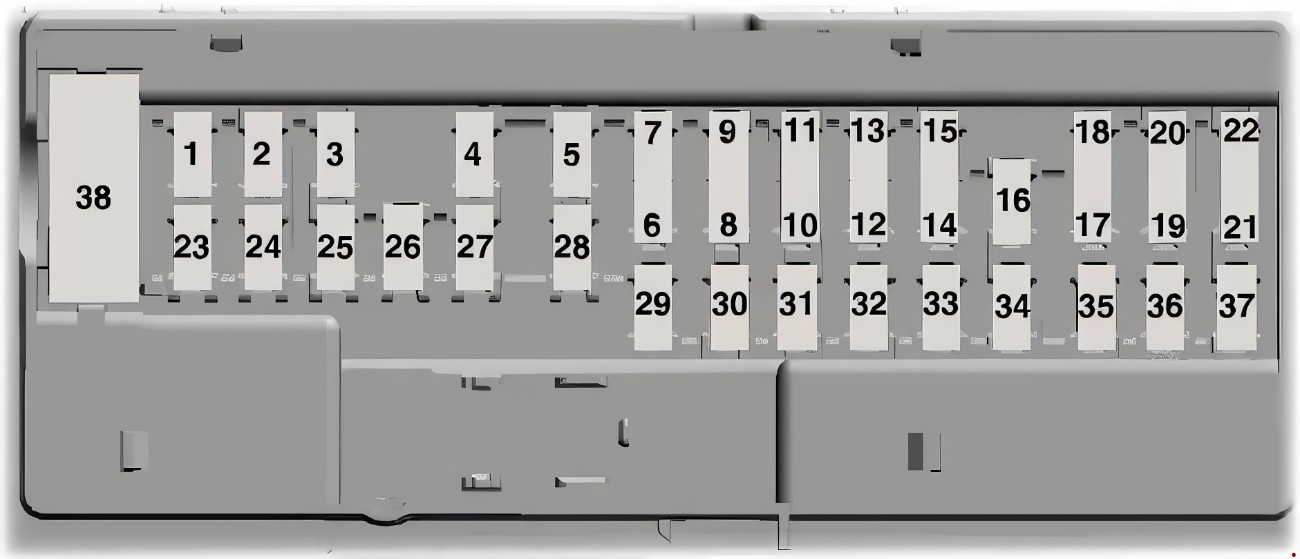
|
Fuse Number
|
Fuse Amperage
|
Fuse Function
|
|
1
|
10A
|
Glove box, power seat relay, demand lamp relay, overhead console, vanity lamps, dome, map lamps and courtesy lamps
|
|
2
|
7.5A
|
Memory seat switches, lumbar motor and memory module logic
|
|
3
|
20A
|
Driver door lock motor
|
|
4
|
5A
|
Trailer brake control
|
|
5
|
20A
|
Not in Use
|
|
6
|
10A
|
Not in Use
|
|
7
|
10A
|
Not in use
|
|
8
|
10A
|
Not in Use
|
|
9
|
10A
|
Not in Use
|
|
10
|
5A
|
Embedded modem module
|
|
11
|
5A
|
Combined sensor module
|
|
12
|
7.5A
|
Climate head module and data link converter
|
|
13
|
7.5A
|
Cluster and SCCM
|
|
14
|
10A
|
Brake
|
|
15
|
10A
|
Smart data link converter
|
|
16
|
15A
|
Tailgate release
|
|
17
|
5A
|
Heads up display (HUD) and terrain switch
|
|
18
|
5A
|
Key inhibit solenoid, passive entry passive start-stop switch
|
|
19
|
7.5A
|
Tow haul (O/D) cancel for floor or column shifter
|
|
20
|
5A
|
Not in Use
|
|
21
|
5A
|
Heads up display (HUD), in case temp with humidity sensor
|
|
22
|
5A
|
Power Seats and EPB
|
|
23
|
10A
|
Driver side window, PDGR switch, Vistaroof and moonroof
|
|
24
|
20A
|
Central lock/unlock
|
|
25
|
30A
|
Driver door control module
|
|
26
|
30A
|
Passenger door control module
|
|
27
|
30A
|
Moonroof and Vista roof
|
|
28
|
20A
|
Not in Use
|
|
29
|
30A
|
Not in Use
|
|
30
|
30A
|
Not in Use
|
|
31
|
15A
|
Adjustable pedal switch and motor
|
|
32
|
10A
|
Radio frequency receiver, SYNC, GPS and multifunction display
|
|
33
|
20A
|
Radio
|
|
34
|
30A
|
Run/start relay
|
|
35
|
5A
|
Restraints module
|
|
36
|
15A
|
Heated steering wheel module, 360 camera module, rear heated seats and rear view mirror
|
|
37
|
20A
|
Power distribution box run/start relay
|
|
Circuit Breaker 38
|
|
Rear window switches and motors
|
Power Distribution Fuse Box

|
Fuse Number
|
Fuse Amperage
|
Fuse Function
|
|
1
|
|
Not in Use
|
|
2
|
|
Not in Use
|
|
3
|
|
Not in Use
|
|
Relay 4
|
|
Telescoping side-view mirror
|
|
5
|
40A
|
Rear window defroster
|
|
6
|
|
Not in Use
|
|
7
|
|
Not in Use
|
|
Relay 8
|
|
Telescoping side-view mirror
|
|
9
|
30A
|
Fuel pump
|
|
10
|
40A
|
Raptor charge air cooler fans
|
|
11
|
60A
|
Automatic brake system motor
|
|
12
|
50A
|
Body control module 1
|
|
13
|
60
|
Body control module 2
|
|
14
|
20A
|
Amplifier
|
|
15
|
25A
|
4x4
|
|
16
|
10A
|
Spotlight module
|
|
17
|
15A
|
Heated seat
|
|
18
|
10A
|
Steering column lock
|
|
19
|
10A
|
Power seats
|
|
20
|
15A
|
Rear heated seats and snowplow
|
|
21
|
15A
|
Transmission control module
|
|
22B
|
|
Not in Use
|
|
22
|
30A
|
Windshield wiper motor
|
|
23
|
15A
|
Rain sensor
|
|
24
|
25A
|
Series fan feed
|
|
25
|
|
Not in Use
|
|
26
|
30A
|
Driver seat motors
|
|
27
|
30A
|
Passenger power seat
|
|
28
|
30A
|
Climate controlled seat
|
|
29
|
25A
|
Raptor upfitter fuses 94,96,98 and 100
|
|
Relay 30
|
|
Air conditioner clutch
|
|
31
|
|
Not in Use
|
|
Relay 32
|
|
Not in Use
|
|
33
|
50A
|
Electric fan 3
|
|
34
|
25A
|
Trailer tow park lamps
|
|
35
|
20A
|
Trailer tow stop/turn relay
|
|
36
|
25A
|
Trailer tow lamps module
|
|
37
|
50A
|
Electric fan 1
|
|
38
|
10A
|
Alt-A sensor
|
|
39
|
10A
|
Integrated wheel end solenoid
|
|
40
|
15A
|
E-locker
|
|
41
|
10A
|
Telescoping mirror
|
|
42
|
30A
|
Transmission fluid pump
|
|
43
|
25A
|
Horn
|
|
44
|
10A
|
Air conditioner clutch
|
|
45
|
10A
|
Powertrain control module relay coil
|
|
46
|
10A
|
Wiper relay coil
|
|
47
|
15A
|
Upfitter for Raptor only
|
|
48
|
15A
|
Upfitter 2 for Raptor only
|
|
49
|
30A
|
Trailer brake control module
|
|
50
|
30A
|
Power running boards
|
|
Relay 51
|
|
Fuel Pump
|
|
52
|
|
Not in Use
|
|
Relay 53
|
|
Upfitter 5 for Raptor only
|
|
54
|
30A
|
Voltage quality module and body control module voltage quality module feed
|
|
55
|
40A
|
Body control module RP2 feed
|
|
56
|
20A
|
Fuel pump
|
|
57
|
30A
|
Right hand EPB actuator
|
|
58
|
30A
|
Left hand EPB actuator
|
|
59
|
30A
|
Starter
|
|
60
|
40A
|
Blower motor
|
|
61
|
30A
|
Brake control module and automatic brake system valves
|
|
Relay 62
|
|
Power seat
|
|
63
|
15A
|
Heated mirrors
|
|
Relay 64
|
|
Upfitter 6 for Raptor only
|
|
Relay 65
|
|
Starter
|
|
Relay 66
|
|
Powertrain control module
|
|
Relay 67
|
|
Windscreen wiper
|
|
Relay 68
|
|
Blower motor
|
|
Relay 69
|
|
Power sliding back window
|
|
Relay 70
|
|
Electric fan T
|
|
71
|
|
Not in Use
|
|
72
|
25A
|
4x4
|
|
73
|
|
Not in Use
|
|
74
|
30A
|
PDGR motor
|
|
Relay 75
|
|
Horn
|
|
76
|
|
Not in Use
|
|
Relay 77
|
|
Steering column lock
|
|
Relay 78
|
|
Not in Use
|
|
Relay 79
|
|
Trailer tow parking lamp
|
|
Relay 80
|
|
Rear window defroster
|
|
Relay 81
|
|
Upfitter 1 for Raptor only
|
|
Relay 82
|
|
PDGR close
|
|
Relay 83
|
|
Upfitter 2 for Raptor only
|
|
84
|
|
Not in Use
|
|
85
|
|
Not in Use
|
|
86
|
|
Not in Use
|
|
87
|
10A
|
Trailer tow backup lamps
|
|
88
|
|
Not in Use
|
|
89
|
20A
|
Cigarette lighter/powerpoint 1
|
|
90
|
20
|
Powerpoint 2
|
|
91
|
20A
|
Powerpoint 3
|
|
92
|
20A
|
Powerpoint 4
|
|
93
|
10A/25A
|
PFI vehicle power 1/GTDI vehicle power 1
|
|
94
|
10A
|
Upfitter for Raptor only
|
|
95
|
25A
|
Vehicle power 2
|
|
96
|
10A
|
Upfitter 4 for Raptor only
|
|
97
|
10A
|
Vehicle power 3
|
|
98
|
5A
|
Upfitter 5 for Raptor only
|
|
99
|
15A/20A
|
GTDI vehicle power 4/PFI vehicle power 4
|
|
100
|
5A
|
Upfitter 6 for Raptor only
|
|
101
|
|
Not in Use
|
|
Relay 102
|
|
Snow plow
|
|
Relay 103
|
|
Charge air cooler fan for Raptor only
|
|
Relay 104
|
|
Fan 3
|
|
105
|
10A
|
Power steering
|
|
106
|
|
Not in Use
|
|
107
|
10A
|
Anti-lock brakes (ABS)
|
|
108
|
|
Not in Use
|
|
109
|
10A
|
PCM, transmission control module run/start power
|
|
110
|
10A
|
Adaptive cruise control and 4x4 run/start
|
|
111
|
15A
|
Transmission pump run/start
|
|
112
|
10A
|
Charger air cooler relay coil run/start for Raptor only
|
|
113
|
7.5A
|
Rearview camera, left-hand blind spot information system, voltage quality module and front & rear view camera
|
|
Relay 114
|
|
Fan 2
|
|
Relay 115
|
|
Upfitter 3 for Raptor only
|
|
Relay 116
|
|
Upfitter 4 for Raptor only
|
2018 Ford F150 Fuse Box Diagram and Explanation
As with all previous years the 2018 Ford F150 truck has 2 different fuse boxes, the passenger compartment and the power distribution boxes. The Passenger Compartment Fuse Box is the same as in the 2015 F150 with a few changes.
In this year's truck however the Power Distribution Fuse Box has been completely overhauled and is all new for 2018.
Passenger Compartment Fuse Box
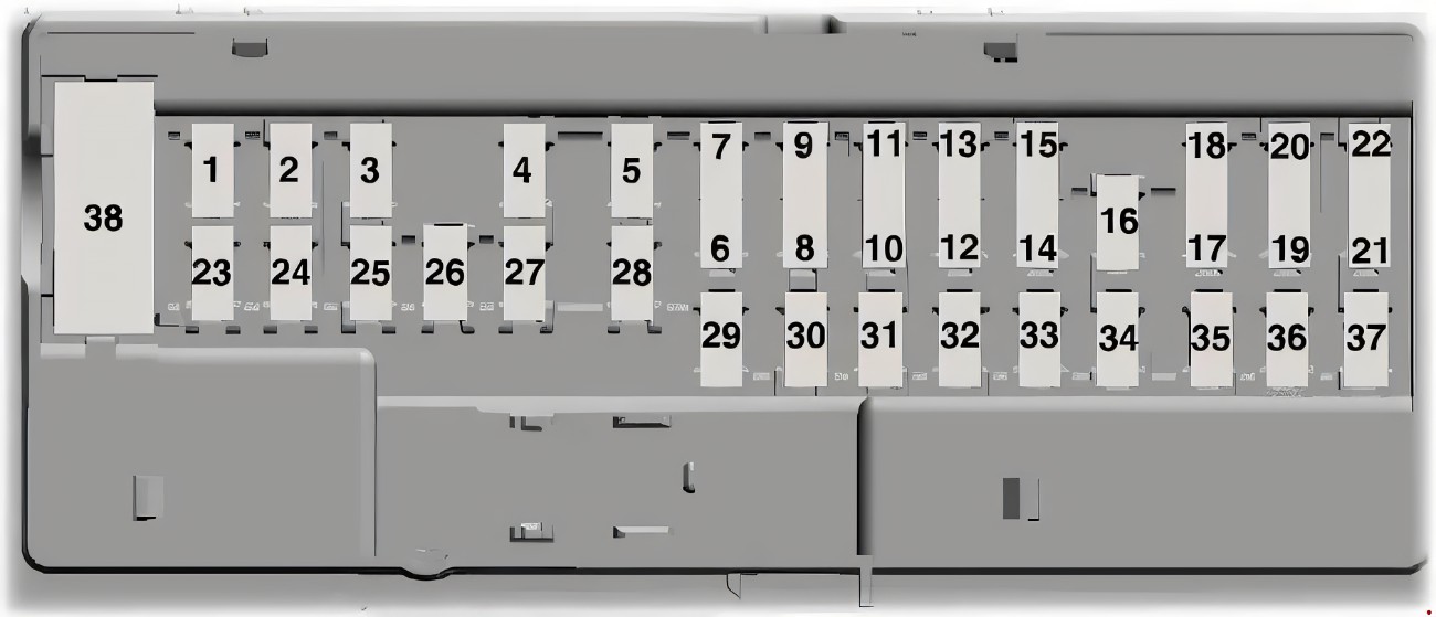
|
Fuse Number
|
Fuse Amperage
|
Fuse Function
|
|
1
|
|
Not in Use
|
|
2
|
7.5A
|
Memory seat switches, lumbar motor and memory module logic
|
|
3
|
20A
|
Driver door lock motor
|
|
4
|
5A
|
Trailer brake control
|
|
5
|
20A
|
Spare not in use
|
|
6
|
10A
|
Spare not in use
|
|
7
|
10A
|
Spare not in use
|
|
8
|
10A
|
Spare not in use
|
|
9
|
10A
|
Extended power module on base only
|
|
10
|
5A
|
Embedded modem module
|
|
11
|
5A
|
Combined sensor module
|
|
12
|
7.5A
|
Climate head module and data link converter
|
|
13
|
7.5A
|
Cluster and SCCM
|
|
14
|
10A
|
Brake on/off switch
|
|
15
|
10A
|
Smart data link converter
|
|
16
|
15A
|
Tailgate release
|
|
17
|
5A
|
Ignition switch and passive entry passive start passive start-stop switch, terrain switch and HUD
|
|
18
|
5A
|
Key inhibit solenoid, passive entry passive start-stop switch
|
|
19
|
7.5A
|
Extended module for non-Raptor or Restraint control module for Raptor only
|
|
20
|
|
Not in Use
|
|
21
|
5A
|
Heads up display (HUD), in case temp with humidity sensor
|
|
22
|
5A
|
Passenger occupant detection for Raptor only
|
|
23
|
10A
|
Driver side window, PDGR switch, Vista roof and moonroof
|
|
24
|
20A
|
Central lock/unlock
|
|
25
|
30A
|
Driver door control module
|
|
26
|
30A
|
Passenger door control module
|
|
27
|
30A
|
Moonroof and Vista roof
|
|
28
|
20A
|
Spare not in use
|
|
29
|
30A
|
Spare not in use
|
|
30
|
30A
|
Spare not in use
|
|
31
|
15A
|
Adjustable pedal switch and motor
|
|
32
|
10A
|
Radio frequency receiver and multifunction display
|
|
33
|
20A
|
Radio
|
|
34
|
30A
|
Run/start relay
|
|
35
|
5A
|
Selectable drive mode switch, upfitter switches on raptor only
|
|
36
|
15A
|
Heated steering wheel module, 360 camera module, Lane departure warning module, the Image processing module A and automatic high beam module rear heated seats and rear view mirror
|
|
37
|
20A
|
Spare but not in use
|
|
Circuit Breaker 38
|
|
Rear window switches and motors
|
Power Distribution Fuse Box
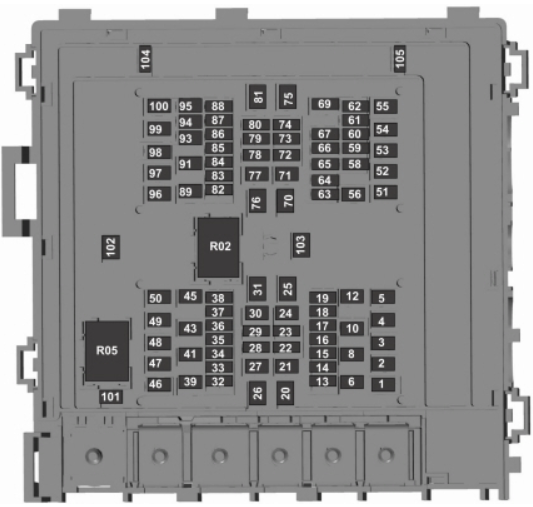
|
Fuse Number
|
Fuse Amperage
|
Fuse Function
|
|
1
|
25A
|
Horn
|
|
2
|
50A
|
Electric fan 1
|
|
3
|
30A
|
Windshield wiper motor
|
|
4
|
60A
|
Body control module
|
|
5
|
30A
|
Starter relay
|
|
6
|
20A
|
Powerpoint 1
|
|
8
|
20A
|
Powerpoint 2
|
|
10
|
5A
|
Rain sensor
|
|
12
|
15A
|
Upfitter 1 Relay for Raptor only
|
|
13
|
10A
|
Adaptive cruise control run/start module and 4x4 run/start
|
|
14
|
15A
|
Spare not in use
|
|
15
|
7.5A
|
Front view camera and voltage quality module (Is a spare fuse in the Raptor)
|
|
16
|
10A
|
Transmission control module run/start and Powertrain control module
|
|
17
|
10A
|
Anti=lock brakes run/start
|
|
18
|
10A
|
Electric power steering run/start
|
|
19
|
5A
|
Upfitter 5 for Raptor only
|
|
20
|
40A
|
Blower motor
|
|
21
|
30A
|
Passenger seat motors
|
|
22
|
20A
|
Radio amplifier
|
|
23
|
10A
|
Alt-A sensor
|
|
24
|
30A
|
Trailer brake control module
|
|
25
|
50A
|
Body control module 1
|
|
26
|
50A
|
Electric fan (gas)
|
|
27
|
30A
|
Driver seat motors and memory module
|
|
28
|
15A
|
Heated seat
|
|
29
|
10A
|
4x4 solenoid
|
|
30
|
25A
|
Trailer tow battery charge
|
|
31
|
|
Not in Use
|
|
32
|
10A
|
Air conditioning clutch
|
|
33
|
|
Not in use
|
|
34
|
10A
|
Vehicle power 5 (diesel)
|
|
35
|
15A/20A
|
Vehicle power 4 (Diesel/Gas)
|
|
36
|
10A
|
Vehicle power 3
|
|
37
|
15A/25A
|
Vehicle power 2 (Diesel/Gas)
|
|
38
|
20A/25A
|
Vehicle power 1 (Diesel/Gas)
|
|
39
|
|
Not in Use
|
|
41
|
30A
|
Body control module and voltage quality module feed
|
|
43
|
20A
|
Trailer tow lamps module
|
|
45
|
|
Not in Use
|
|
46
|
10A
|
Steering Column lock
|
|
47
|
50A
|
Power control heater 3 (diesel)
|
|
48
|
30A
|
Fuel filter heater (diesel)
|
|
49
|
30A
|
Not in Use
|
|
50
|
30A
|
Fuel Pump
|
|
51
|
20A
|
Powerpoint 3
|
|
52
|
50A
|
Powertrain control heater 2 (diesel)
|
|
53
|
25A
|
Trailer tow park lamps
|
|
54
|
|
Not in Use
|
|
55
|
15A
|
Upfitter 2 relay for Raptor only
|
|
56
|
|
Not in Use
|
|
58
|
5A
|
USB smart charger
|
|
59
|
|
Not in Use
|
|
60
|
|
Not in Use
|
|
61
|
15A
|
Spare not in use
|
|
62
|
5A
|
Upfitter 6 for Raptor only
|
|
63
|
25A
|
4x4
|
|
64
|
15A
|
E-locker
|
|
65
|
|
Not in Use
|
|
66
|
|
Not in Use
|
|
67
|
|
Not in Use
|
|
69
|
|
Not in Use
|
|
70
|
40A
|
Electric parking brake and ABS valves
|
|
71
|
25A
|
4x4
|
|
72
|
|
Not in Use
|
|
73
|
|
Not in Use
|
|
74
|
10A
|
Trailer tow backup lamps
|
|
75
|
|
Not in Use
|
|
76
|
40A
|
Body control module 2
|
|
77
|
30A
|
Climate controlled seats
|
|
78
|
10A
|
Spotlight module
|
|
79
|
|
Not in Use
|
|
80
|
10A
|
Heated windshield wiper (Upfitter 4 Relay Raptor only)
|
|
81
|
|
Not in Use
|
|
82
|
30A
|
Transmission fluid pump (Power control module diesel engines only)
|
|
83
|
15A
|
Transmission control module
|
|
84
|
|
Not in Use
|
|
85
|
|
Not in Use
|
|
86
|
|
Not in Use
|
|
87
|
|
Not in Use
|
|
88
|
10A
|
Multi-contour seat relay (Upfitter 3 Raptor only)
|
|
89
|
30A
|
Power running boards
|
|
91
|
|
Not in Use
|
|
93
|
15A
|
Heated mirrors
|
|
94
|
15A
|
Rear heated seat module (Raptor, diesel)
|
|
95
|
15A
|
Spare not in use
|
|
96
|
|
Not in Use
|
|
97
|
40A
|
Powertrain control heater 1 (diesel)
|
|
98
|
15A
|
3.3L transmission fluid pump, 10R transmission module
|
|
99
|
40A
|
Heated rear window
|
|
100
|
25A
|
Diesel exhaust fluid heater relay
|
|
101
|
25A
|
Electric fan (base only)
|
|
102
|
30A
|
Powersliding back window
|
|
103
|
20A
|
Trailer tow stop-turn relay
|
|
104
|
10A
|
Rear heated seats (base) and snowplow switch
|
|
105
|
10A
|
Telescoping mirror
|
|
Relay R02
|
|
Powertrain control module
|
|
Relay R05
|
|
Electric fan
|
2019-2020 Ford F150 Fuse Box Diagram and Explanation
The 2019-2020 model year of the Ford F150 featured the same two fuse boxes as the 2018 model but with some further changes. The Passenger Compartment Fuse Box comes from the 2015 Ford F150 but has greatly changed while the power distribution box is based off of the 2018 model year.
Passenger Compartment Fuse Box
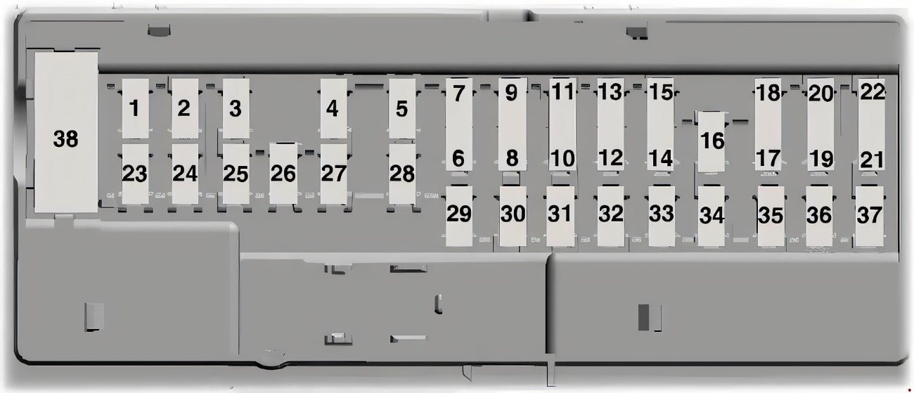
|
Fuse Number
|
Fuse Amperage
|
Fuse Function
|
|
1
|
|
Not in Use
|
|
2
|
7.5A
|
Memory seat switches, lumbar motor and memory module logic
|
|
3
|
20A
|
Driver door lock motor
|
|
4
|
5A
|
Trailer brake control
|
|
5
|
20A
|
Spare not in use
|
|
6
|
10A
|
Spare not in use
|
|
7
|
10A
|
Spare not in use
|
|
8
|
10A
|
Spare not in use
|
|
9
|
10A
|
Extended power module on base only
|
|
10
|
5A
|
Embedded modem module
|
|
11
|
5A
|
Combined sensor module
|
|
12
|
7.5A
|
Climate head module and data link converter
|
|
13
|
7.5A
|
Cluster and SCCM
|
|
14
|
10A
|
Brake on/off switch
|
|
15
|
10A
|
Smart data link converter
|
|
16
|
15A
|
Tailgate release
|
|
17
|
5A
|
Terrain switch and heads up display
|
|
18
|
5A
|
Key inhibit solenoid, passive entry passive start-stop switch
|
|
19
|
7.5A
|
Extended power module for non-Raptor or Restraint control module for Raptor only
|
|
20
|
|
Not in Use
|
|
21
|
5A
|
Heads up display (HUD), in case temp with humidity sensor
|
|
22
|
5A
|
Passenger occupant detection for Raptor only
|
|
23
|
10A
|
Driver side window, PDGR switch, Vista roof and moonroof
|
|
24
|
20A
|
Central lock/unlock
|
|
25
|
30A
|
Driver door control module
|
|
26
|
30A
|
Passenger door control module
|
|
27
|
30A
|
Moonroof and Vista roof
|
|
28
|
20A
|
Spare not in use
|
|
29
|
30A
|
Spare not in use
|
|
30
|
30A
|
Spare not in use
|
|
31
|
15A
|
Adjustable pedal switch and motor
|
|
32
|
10A
|
Radio frequency receiver and multifunction display
|
|
33
|
20A
|
Radio
|
|
34
|
30A
|
Run/start relay
|
|
35
|
5A
|
Selectable drive mode switch, upfitter switches on Raptor only
|
|
36
|
15A
|
Heated steering wheel module, 360 camera module, Lane departure warning module, the Image processing module A and automatic high beam module rear heated seats and rear view mirror
|
|
37
|
20A
|
Spare but not in use
|
|
Circuit Breaker 38
|
|
Rear window switches and motors
|
Power Distribution Fuse Box
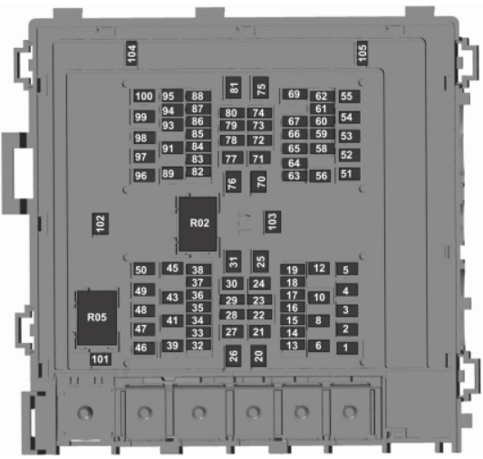
|
Fuse Number
|
Fuse Amperage
|
Fuse Function
|
|
1
|
25A
|
Horn
|
|
2
|
50A
|
Electric fan 1
|
|
3
|
30A
|
Windshield wiper motor
|
|
4
|
60A
|
Body control module
|
|
5
|
30A
|
Starter relay
|
|
6
|
20A
|
Powerpoint 1
|
|
8
|
20A
|
Powerpoint 2
|
|
10
|
5A
|
Rain sensor
|
|
12
|
15A
|
Upfitter 1 Relay for Raptor only
|
|
13
|
10A
|
Adaptive cruise control run/start module and 4x4 run/start
|
|
14
|
15A
|
Spare on Raptor
|
|
15
|
7.5A
|
Front view camera and voltage quality module (Is a spare fuse in the Raptor)
|
|
16
|
10A
|
Transmission control module run/start and Powertrain control module
|
|
17
|
10A
|
Anti=lock brakes run/start
|
|
18
|
10A
|
Electric power steering run/start
|
|
19
|
5A
|
Upfitter 5 for Raptor only
|
|
20
|
40A
|
Blower motor
|
|
21
|
30A
|
Passenger seat motors
|
|
22
|
20A
|
Radio amplifier
|
|
23
|
10A
|
Alt-A sensor
|
|
24
|
30A
|
Trailer brake control module
|
|
25
|
50A
|
Body control module 1
|
|
26
|
50A
|
Electric fan (gas)
|
|
27
|
30A
|
Driver seat motors and memory module
|
|
28
|
15A
|
Heated seat
|
|
29
|
10A
|
4x4 solenoid
|
|
30
|
25A
|
Trailer tow battery charge
|
|
31
|
|
Not in Use
|
|
32
|
10A
|
Air conditioning clutch
|
|
33
|
|
Not in use
|
|
34
|
10A
|
Vehicle power 5 (diesel)
|
|
35
|
15A/20A
|
Vehicle power 4 (Diesel/Gas)
|
|
36
|
10A
|
Vehicle power 3
|
|
37
|
15A/25A
|
Vehicle power 2 (Diesel/Gas)
|
|
38
|
25A
|
Vehicle power 1 (Diesel/Gas)
|
|
39
|
|
Not in Use
|
|
41
|
30A
|
Body control module and voltage quality module feed
|
|
43
|
20A
|
Trailer tow lamps module
|
|
45
|
|
Not in Use
|
|
46
|
10A
|
Steering Column lock
|
|
47
|
50A
|
Power control heater 3 (diesel)
|
|
48
|
30A
|
Fuel filter heater (diesel)
|
|
49
|
|
Not in Use
|
|
50
|
30A
|
Fuel Pump
|
|
51
|
20A
|
Powerpoint 3
|
|
52
|
50A
|
Powertrain control heater 2 (diesel)
|
|
53
|
25A
|
Trailer tow park lamps
|
|
54
|
|
Not in Use
|
|
55
|
15A
|
Upfitter 2 relay for Raptor only
|
|
56
|
|
Not in Use
|
|
58
|
5A
|
USB smart charger
|
|
59
|
|
Not in Use
|
|
60
|
|
Not in Use
|
|
61
|
15A
|
Spare not in use (Raptor)
|
|
62
|
5A
|
Upfitter 6 for Raptor only
|
|
63
|
25A
|
4x4
|
|
64
|
15A
|
E-locker
|
|
65
|
|
Not in Use
|
|
66
|
|
Not in Use
|
|
67
|
|
Not in Use
|
|
69
|
|
Not in Use
|
|
70
|
40A
|
Electric parking brake and ABS valves
|
|
71
|
25A
|
4x4
|
|
72
|
|
Not in Use
|
|
73
|
|
Not in Use
|
|
74
|
10A
|
Trailer tow backup lamps
|
|
75
|
|
Not in Use
|
|
76
|
40A
|
Body control module 2
|
|
77
|
30A
|
Climate controlled seats
|
|
78
|
10A
|
Spotlight module
|
|
79
|
|
Not in Use
|
|
80
|
10A
|
Heated windshield wiper (Upfitter 4 Relay Raptor only)
|
|
81
|
|
Not in Use
|
|
82
|
30A
|
Transmission fluid pump (Power control module diesel engines only)
|
|
83
|
15A
|
Transmission control module
|
|
84
|
|
Not in Use
|
|
85
|
|
Not in Use
|
|
86
|
|
Not in Use
|
|
87
|
|
Not in Use
|
|
88
|
10A
|
Multi-contour seat relay (Upfitter 3 Raptor only)
|
|
89
|
30A
|
Power running boards
|
|
91
|
|
Not in Use
|
|
93
|
15A
|
Heated mirrors
|
|
94
|
15A
|
Rear heated seat module (Raptor, diesel)
|
|
95
|
15A
|
Spare not in use (Raptor)
|
|
96
|
|
Not in Use
|
|
97
|
40A
|
Powertrain control heater 1 (diesel)
|
|
98
|
15A
|
3.3L transmission fluid pump, 10R transmission module
|
|
99
|
40A
|
Heated rear window
|
|
100
|
25A
|
Diesel exhaust fluid heater relay
|
|
101
|
25A
|
Electric fan (base only)
|
|
102
|
30A
|
Powersliding back window
|
|
103
|
20A
|
Trailer tow stop-turn relay
|
|
104
|
10A
|
Rear heated seats (base) and snowplow switch
|
|
105
|
10A
|
Telescoping mirror
|
|
Relay R02
|
|
Powertrain control module
|
|
Relay R05
|
|
Electric fan
|
2021-2022 Ford F150 Fuse Box Diagram and Explanation
We have finally reached the most recent model year, the 2021-2022 Ford F150 which believe it or not just like all the others still has two fuse boxes. These fuse boxes can still be found in the same place and can be easily accessed by removing the protective panels.
In this model year both fuse boxes have been completely updated so let's take a look at what these fuses all mean. Hopefully you won’t need to know this for a long time and your new F150 has no issues.
Passenger Compartment Fuse Box
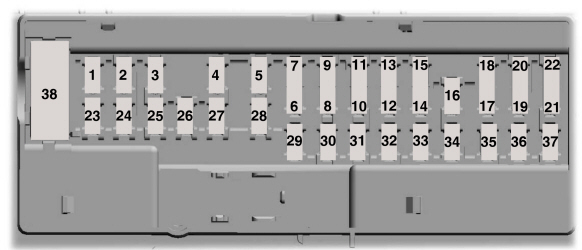
|
Fuse Number
|
Fuse Amperage
|
Fuse Function
|
|
1
|
|
Not in Use
|
|
2
|
10A
|
Accessory feed
|
|
3
|
7.5A
|
Wireless charger
|
|
4
|
|
Not in Use
|
|
5
|
|
Not in Use
|
|
6
|
10A
|
Driver power window switch
|
|
7
|
10A
|
Gear shift module
|
|
8
|
5A
|
Cell phone passport module
|
|
9
|
5A
|
Combined sensor module
|
|
10
|
|
Not in Use
|
|
11
|
|
Not in Use
|
|
12
|
7.5A
|
Enhanced central gateway and climate control
|
|
13
|
7.5A
|
Instrument cluster and steering column control module (SCCM)
|
|
14
|
15A
|
Spare not in use
|
|
15
|
15A
|
Integrated control panel, SYNC
|
|
16
|
|
Not in Use
|
|
17
|
7.5A
|
Headlamp control module
|
|
18
|
7.5A
|
Not in Use
|
|
19
|
5A
|
Headlamp switch
|
|
20
|
5A
|
Passive start, key inhibit solenoid and ignition switch
|
|
21
|
5A
|
Trailer brake switch
|
|
22
|
5A
|
Not in Use
|
|
23
|
30A
|
Driver door control module
|
|
24
|
30A
|
Moonroof
|
|
25
|
|
Not in Use
|
|
26
|
30A
|
Passenger door control module
|
|
27
|
30A
|
Not in Use
|
|
28
|
30A
|
Amplifier
|
|
29
|
15A
|
Adjustable pedals and 12-inch display
|
|
30
|
|
Not in Use
|
|
31
|
10A
|
RF receiver and driver monitor terrain management switch
|
|
32
|
20A
|
Audio control module
|
|
33
|
|
Not in Use
|
|
34
|
30A
|
Run/start relay
|
|
35
|
5A
|
400-watt inverter run/start
|
|
36
|
15A
|
Auto-dimming interior mirror, adaptive front steering run/start, heated wheel
|
|
37
|
20A
|
Advanced driver assistance systems
|
|
Circuit Breaker 38
|
30A
|
Rear power windows
|
Power Distribution Fuse Box

|
Fuse Number
|
Fuse Amperage
|
Fuse Function
|
|
1
|
40A
|
Battery control module, battery power feed 1
|
|
3
|
40A
|
Battery control module, battery power feed 2
|
|
4
|
30A
|
Fuel pump
|
|
5
|
5A
|
Powertrain control module coil
|
|
6
|
25A
|
Powertrain control module power (gas, hybrid)
|
|
7
|
20A
|
Powertrain control module power
|
|
8
|
10A/20A
|
Powertrain control module power (gas, diesel, raptor, tremor)/Powertrain control module power (hybrid)
|
|
9
|
20A
|
Powertrain control module power (gas, hybrid)
|
|
10
|
20A
|
Powertrain control module power (diesel)
|
|
11
|
30A
|
Starter motor
|
|
13
|
40A
|
Blower motor
|
|
15
|
25A
|
Horn
|
|
19
|
20A
|
Snow plow switch (gas), Rear heated seats (gas, diesel, hybrid).
|
|
21
|
10A
|
Headlamp run/start feed
|
|
22
|
10A
|
Electronic power assist steering
|
|
23
|
10A
|
Electric brake boost
|
|
24
|
10A
|
Powertrain control module (gas, hybrid), Transmission control module (diesel), Glow plug control module (diesel).
|
|
25
|
10A
|
Center high-mounted stop lamp camera.Trailer camera. 2 kW inverter.24 V alternator - run/start feed.Analog rear video camera.
|
|
28
|
50A
|
Electric brake boost
|
|
29
|
50A
|
Electric brake boost
|
|
30
|
40A
|
Driver power seat.
|
|
31
|
30A
|
Passenger power seat.
|
|
32
|
20A
|
Auxiliary power point.
|
|
33
|
20A
|
Auxiliary power point.
|
|
34
|
20A
|
Auxiliary power point.
|
|
37
|
30A
|
Tailgate module.
|
|
38
|
40A
|
Climate controlled seat module and power running boards
|
|
41
|
25A
|
Power sliding back window.
|
|
42
|
30A
|
Trailer brake control module.
|
|
47
|
50A
|
Cooling fan (gas, hybrid, Raptor, Tremor).
|
|
48
|
20A
|
Rear heated seats (Raptor, Tremor)
|
|
49
|
50A
|
Cooling fan (gas, hybrid, Raptor, Tremor).
|
|
50
|
40A
|
Heated backlight (gas, hybrid).
|
|
55
|
30A
|
Trailer tow park lamps.
|
|
56
|
20A
|
Trailer tow stop and tum lamps (4-pin connector).
|
|
58
|
10A
|
Trailer tow backup lamps.
|
|
60
|
15A
|
Upfitter relay (Raptor, Tremor).
|
|
61
|
15A
|
Upfitter 2 relay (Raptor, Tremor).
|
|
62
|
10A
|
Upfitter 3 relay (Raptor, Tremor).
|
|
63
|
10A
|
Upfitter 4 relay (Raptor, Tremor).
|
|
64
|
25A
|
Four-wheel drive.
|
|
65
|
15A
|
Transmission control module (diesel).
|
|
67
|
20A
|
Transmission run/start.
|
|
69
|
30A
|
Left-hand windshield wiper.
|
|
82
|
25A
|
Four-wheel drive.
|
|
83
|
50A
|
Supplemental heater (diesel).
|
|
84
|
50A
|
Supplemental heater (diesel).
|
|
85
|
50A
|
Supplemental heater (diesel).
|
|
86
|
25A
|
Selective catalytic reduction system (diesel).
|
|
91
|
20A
|
Trailer tow light module.
|
|
95
|
15A
|
Powertrain control module power (hybrid).
|
|
98
|
10A
|
Powertrain control module power (hybrid), coolant pumps (hybrid)
|
|
100
|
15A
|
Left-hand headlamps.
|
|
101
|
15A
|
Right-hand headlamps.
|
|
105
|
50A
|
Active front steering.
|
|
107
|
30A
|
Trailer tow battery charge.
|
|
108
|
15A
|
Spot lamps (police).
|
|
121
|
30A
|
Fuel filter heater (diesel).
|
|
124
|
5A
|
Rain sensor module.
|
|
125
|
10A
|
USB smart charger.
|
|
134
|
25A
|
Multi-contour seats relay (gas, diesel, hybrid).
|
|
138
|
10A
|
Tailgate release.
|
|
139
|
5A
|
USB smart charger.
|
|
146
|
15A
|
Traction battery control module (hybrid).
|
|
147
|
40A
|
Change air cooler fan relay (Raptor, Tremor).
|
|
159
|
5A
|
DC/DC power (hybrid).
|
|
160
|
10A
|
Smart data link control.
|
|
168
|
15A
|
Traction battery control module (hybrid).
|
|
169
|
10A
|
Motor electric cool pump (hybrid).
|
|
170
|
10A
|
Pedestrian alert control module (hybrid). Traction battery control module (hybrid), Electric motor cool pump (hybrid).
|
|
202
|
60A
|
Body control module B+.
|
|
210
|
30A
|
Body control module start stop.
|
|
305
|
5A
|
Upfitter 5 relay (Raptor, Tremor).
|
|
306
|
5A
|
Upfitter 6 relay (Raptor, Tremor).
|
|
R04
|
|
Electronic fan relay 1.
|
|
R06
|
|
Electronic fan relay 3.
|
|
R35
|
|
Supplemental heater (diesel).
|
|
R36
|
|
Supplemental heater (diesel).
|
Conclusion
There have been a number of fuse box changes in the Ford F150 range since 1999 until today but some model years did use the same layouts. Generally speaking each year there would be some changes made to how the fuses were used.
This was due to the ever growing technology in our trucks and a higher reliance on electrical elements. Hopefully the above run through of all the model years will help you locate whichever fuses in your Ford F150 that may be causing you a problem.
Link To or Reference This Page
We spend a lot of time collecting, cleaning, merging, and formatting the data that is shown on the site to be as useful to you as possible.
If you found the data or information on this page useful in your research, please use the tool below to properly cite or reference Tow Ratings as the source. We appreciate your support!
-
<a href="http://towratings.net/blog/ford-f150-fuse-box-diagram-1999-to-2021/">Ford F150 Fuse Box Diagram (1999 to 2021)</a>
-
"Ford F150 Fuse Box Diagram (1999 to 2021)". Tow Ratings. Accessed on April 26, 2024. http://towratings.net/blog/ford-f150-fuse-box-diagram-1999-to-2021/.
-
"Ford F150 Fuse Box Diagram (1999 to 2021)". Tow Ratings, http://towratings.net/blog/ford-f150-fuse-box-diagram-1999-to-2021/. Accessed 26 April, 2024
-
Ford F150 Fuse Box Diagram (1999 to 2021). Tow Ratings. Retrieved from http://towratings.net/blog/ford-f150-fuse-box-diagram-1999-to-2021/.


